Current Source Amp using [R085]
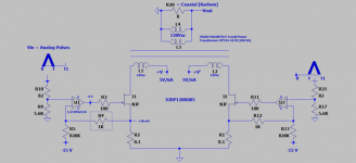
The attached schematic of the subject amp shows I increased the power of the PSU rail. I use two independent +5/6A PSUs [twins]. Each is a linear design and is regulated; salvaged from an old computer. This use simulates using future 5V SMPSs.
This amp is a current hog; by choice and by suggested design. Its by-ear musical fidelity followed this trend for PSUs used: Twin 5V/6A>Single 5V/6A>5V/2A. Made sense.
Here's a suggested calculation for the power of this amp; focus on one [R085]:
1. Maximum DC power is 5V X 6A = 30W
2. RMS power is 30W X 0.707 = 21W
3. Factor an 80% efficiency transform for the power toroid: 21W X 0.8 = 17W
4. This 17W rms power is expected to be lower because [R085] may need to stay or operate active and not be saturated. A certain value of remnant dynamic Drain-Source equal to 1-2 V may be needed. Subjective performance at such low values of Vds can be assessed by using a 25VA instead of a 100VA power toroid, and increasing acoustic power output; to force saturation.
The sound of this amp [twin PSU rails] expressed by the Karlson [8 Ohm] is highly detailed and dynamic.
The JFETs are on a heat sink. They run cold.
Best
Anton
Attachments
Current Source Amp using [R085]
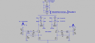
The attached schematic shows that I doubled the original VA of the power output transformer to 200 VA. I have a second 100 VA twin toroid, and so I connected the windings of both toroids in parallel. I essentially halved the load impedance to each [R085]; so it allows the FET to pass more current thru it.
Please note how I connected the load windings at the drains of [R085]. I crossed the connections [color coded] so as to defeat any asymmetry in their manufacture. I do not know if the two windings are wound in a symmetrical manner around the form or not!
I added a Shottky diode as shown across each net load winding because the load to each [R085] is reactive.
This design sounded the best/cleanest and the loudest among the other variations tested.
I searched Bing for "Solar Inverter" which was quoted in the spec. sheet of [R085]. The schematic of the power output stage of this amp is very much like that of a general solar inverter.
Best wishes
Anton
Attachments
Class aP Current Source Amp Using 2SK82 SIT
SJDP120R085 [R085] is a JFET. It works as a voltage variable current source; likened to the operation of pentodes. Its has an RdsOn = 75 milliOhms.
By comparison, 2SK82 is a SIT. It works as a voltage variable resistor; likened to the operation of triodes. It has an RdsON = 1 Ohm.
Ideally, a similar RdsON for the two transistors is best to compare their very different structures as the sole variable. Please advise the name of a SIT which fits. Thank you.
The attached schematic is pretty much the same as the one I've already shown for [R085]; but it uses 2SK82s instead.
Please note:
1. Vds at idle is 5 V for each SIT.
2. Idle current [Idss] is ~130 mA.
2a. The two resistors [750 Ohms//2.2K] encased in a rectangle for the right SIT schematic were used to equalize the idle Idss for both SITs.
Its music expressed by the Karlson [highly efficient] sounds great and is different [by memory] from that of [R085]; noting that both prototype amps sounded equally great.
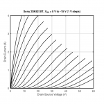
Please note the following operation for this SIT use on its attached graph; which I lifted from another post. Operation departs from the great works of SONY, Yamaha, Mr. Pass, countless DIYers and others.
1. Find 5 V on the X axis of Drain- Source Volts.
2. Erect a perpendicular line to cross the uppermost Vgs =0 V curve.
3. Close the rectangle at a drain current of ~3 A.
Clearly a different use regime. It works without any problems. The SITs on their small heat sink run cold.
Best wishes
Anton
SJDP120R085 [R085] is a JFET. It works as a voltage variable current source; likened to the operation of pentodes. Its has an RdsOn = 75 milliOhms.
By comparison, 2SK82 is a SIT. It works as a voltage variable resistor; likened to the operation of triodes. It has an RdsON = 1 Ohm.
Ideally, a similar RdsON for the two transistors is best to compare their very different structures as the sole variable. Please advise the name of a SIT which fits. Thank you.
The attached schematic is pretty much the same as the one I've already shown for [R085]; but it uses 2SK82s instead.
Please note:
1. Vds at idle is 5 V for each SIT.
2. Idle current [Idss] is ~130 mA.
2a. The two resistors [750 Ohms//2.2K] encased in a rectangle for the right SIT schematic were used to equalize the idle Idss for both SITs.
Its music expressed by the Karlson [highly efficient] sounds great and is different [by memory] from that of [R085]; noting that both prototype amps sounded equally great.
Please note the following operation for this SIT use on its attached graph; which I lifted from another post. Operation departs from the great works of SONY, Yamaha, Mr. Pass, countless DIYers and others.
1. Find 5 V on the X axis of Drain- Source Volts.
2. Erect a perpendicular line to cross the uppermost Vgs =0 V curve.
3. Close the rectangle at a drain current of ~3 A.
Clearly a different use regime. It works without any problems. The SITs on their small heat sink run cold.
Best wishes
Anton
Attachments
![Class aP [SIT]; 2SK82 Current Source Amp.png](/community/data/attachments/877/877079-4e280dfe11dd542ab8498654d394e8d8.jpg)
Class aP Current Source Amp using BJT.
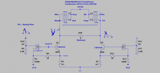
My previous posts showed that I used a transformer to extract output power from the prototype amplifiers.
The attached shematics shows that I reconfigured the transformer windings to become two coils. Done by connecting one primary with one secondary in parallel and in phase.
The Karlson load bridges the collectors of the BJTs; meaning, this prototype amp direct-couples the load.
Class aP grants the option to use one signal only; shown [0 to t] so as to understand the works. The scope traces [not drawn to scale] show the Karlson is sandwiched between two bipolar signals. The N at the peak or bottom of these output signals suggests amplification noise or distortion.
A Darlington is better used instead of a single NPN. It'll ease the current drive from the OpAmp.
The Karlson sounds great.
Best
Anton
Attachments
Class aP Current Source Amp
My last six Class aP schematics are:
1. Symmetrical like a classical Class B.
2. Each semiconductor does not cutoff in operation unlike Class B.
3. The right-side half-circuit does not talk to the left-side half-circuit and vice versa like Class B. Neither side is aware of the other's works.
The attached schematic shows a cross-coupled prototype amp. The two sides now talk to each other.
There's a practical consequence for this cross talk. One side may cutoff the idle of the other side; thus moving operation to Class B.
Here's a practical example:
1. Grant the left side only an input analog pulse signal [0 to t].
2. The depicted signals are not scale; their relative phase is relevant.
3. Let the value of the signal at the emitter of the left BJT = +500 mV peak. This translates to 5 A peak acroos its 0.1 Ohm degeneration resistor.
4. This positive-going signal is routed to the inverting port of the rightside OpAmp. It is attenuated by a factor of 33 to give -15 mVp at the emitter of its [rightside] power BJT.
5. But note: The idle bias of +15 mV at the emitter is completely cancelled by the negative-going -15 mV peak analog pulse. The rightside BJT is cutoff.
6. Increase idle bias from +15 mV [150 mA across 0.1 Ohm] to +25 mV to leave a spare +100 mA idle for the rightside BJT.
The Karlson sounded great and different with and without cross talk [with +25 mV idle] with both BJTs receiving input analog pulses.
Best wishes
Anton
Attachments
Compounding a Class aP current source amp with a voltage source amp
In general, current source amps [CSA] have a higher output impedance than regular voltage source amps [VSA]. CSA is well suited to drive full range [FR] loudspeakers [no or special crossovers], but not the common multiways which embody crossovers designed and geared to work with VSAs. They sound unbalanced and poor.
The objective of compounding a CSA with a VSA is to:
1. Lower the output impedance seen by the load; say down to 0.5 Ohms or less.
2. Damp the loudspeaker's woofer because of VSA's established control action.
3. Create other attributes; but not performance ills like oscillation .
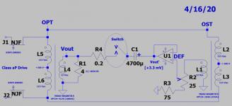
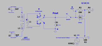
The attached schematic shows a compound prototype from a year ago. Here's an explanation of its works.
1.The left side of the schematic shows a Class aP transformer-coupled power output CSA which uses [R085]; much like that for a vacuum tube. No loop feedback [NFB] is used. The secondary winding of [OPT=100 VA] drives an [FR] loudspeaker [no crossover].
2. The right side of the schematic shows another output signal transformer [OST =25 VA] which is wired parallel to [OPT] as exactly shown. [OST] generates a line level signal to feed the input of DEF which is a buffer.
3. Most important is the phase and amplitude of the power output signals across the load [from CSA] and at the ouput of DEF [VSA] be equal before closing the switch which joins both power amps. The voltage divider and volume control across [OST] do this; with the help of a function generator in the range of 40 to 250 Hz.
4. A low output impedance develops across the load after closing the switch which joins both amps. The woofer cone is damped and the compound amp does not oscillate.
This is a situation whereby a [CSA] controls a [VSA] of equal output power and grants music the stated objective.
To test: Open switch which links both amps. Uses an 8 Ohm 3-way loudspeaker which has a [VSA]-style crossover. Drive/play music only via the secondary winding of [OPT]. Unblanced and poor; torture. Close switch while the music plays. The sound of the loudspeaker becomes normal. Clean, crisp and pleasing.
I'll post an updated version of the attached schematic.
Best wishes
Anton
In general, current source amps [CSA] have a higher output impedance than regular voltage source amps [VSA]. CSA is well suited to drive full range [FR] loudspeakers [no or special crossovers], but not the common multiways which embody crossovers designed and geared to work with VSAs. They sound unbalanced and poor.
The objective of compounding a CSA with a VSA is to:
1. Lower the output impedance seen by the load; say down to 0.5 Ohms or less.
2. Damp the loudspeaker's woofer because of VSA's established control action.
3. Create other attributes; but not performance ills like oscillation .
The attached schematic shows a compound prototype from a year ago. Here's an explanation of its works.
1.The left side of the schematic shows a Class aP transformer-coupled power output CSA which uses [R085]; much like that for a vacuum tube. No loop feedback [NFB] is used. The secondary winding of [OPT=100 VA] drives an [FR] loudspeaker [no crossover].
2. The right side of the schematic shows another output signal transformer [OST =25 VA] which is wired parallel to [OPT] as exactly shown. [OST] generates a line level signal to feed the input of DEF which is a buffer.
3. Most important is the phase and amplitude of the power output signals across the load [from CSA] and at the ouput of DEF [VSA] be equal before closing the switch which joins both power amps. The voltage divider and volume control across [OST] do this; with the help of a function generator in the range of 40 to 250 Hz.
4. A low output impedance develops across the load after closing the switch which joins both amps. The woofer cone is damped and the compound amp does not oscillate.
This is a situation whereby a [CSA] controls a [VSA] of equal output power and grants music the stated objective.
To test: Open switch which links both amps. Uses an 8 Ohm 3-way loudspeaker which has a [VSA]-style crossover. Drive/play music only via the secondary winding of [OPT]. Unblanced and poor; torture. Close switch while the music plays. The sound of the loudspeaker becomes normal. Clean, crisp and pleasing.
I'll post an updated version of the attached schematic.
Best wishes
Anton
Attachments
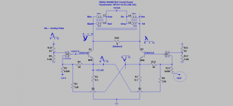
A compound Class aP CSA amp with a VSA amp
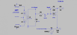
The attached schematic is for the experimental prototype. It is much like the one in the previous post in both structure and operation. Here are additional details
1. The left side of the schematic [CSA] is simplified and is the same as the complete one in post #260.
2. The right side of the schematic shows a standard VSA; with voltage gain and not a unity gain like used in the previous post.
In operation, there is no guarantee that the magnitude of [CSA] Vout equals [VSA] Vout', and their signal phases are aligned. The reactive nature and frequency dependance of the loudspeaker are at play. Thus; the desired bootstrapping [perfect alignment] is variable, and both amps are likely to dump valuable power into each other.
The practical path forward is to make [VSA] Vout' slightly greater in magnitude than [CSA] Vout. I do this in the frequency range of 40 to 250 Hz, and still observe flipping of magnitude; whereby [CSA] Vout at some frequency becomes greater in magnitude than [VSA] Vout'. An inescapable dynamic.
The sound of the Karlson before [CSA only] and after joining both amps [compound] are different. I like the the sound of the compound better; probably due to the definite contribution of VSA. The compound amp does not oscillate; noting some possible positive feedback around VSA; because VSA dumps power in [OPT] which then gets recycled back to VSA via [OST].
Best wishes
Anton
Attachments
Compound Current and independent Voltage source amps. Part 1
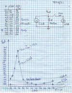
Attached are the schematic, and an objective performance of the current compound [CSA + VSA] prototype. Please note:
A. The schematic is different from the one in the previous post.
B. The tabulated data, the simple schematic of operation which generated the data and the resultant graphed performance. In operation:
1. By example at F= 110 Hz, Vout was measured at [136] with an AC voltmeter.
2. The output voltage of VSA was then made equal in magnitude to that of CSA for this experiment. The 25 Ohm pot in the schematic enabled this adjustment. It was a stable setting. Both signals were in phase and of equal amplitude before the switch is closed. This "equalizing: adjustment was untouched moving forward.
3. The switch was closed and gave a resultant Vout = [138]. I did not detect a difference in sound pressure from the Karlson.
4. Vout data from [CSA] only and from [CSA +VSA] were graphed as a function of frequency.
4a. CSA only [switch off] generated the characteristic plot of the Impedance versus Frequency for a woofer [detailed too]. The resonance frequency was at ~67 Hz. Note the location of an 8 Ohm power resistor on the graph which matched [Vout = 157] at 80 Hz. It allowed calculating Z resonance = 15 Ohms.
5. The graph of the data post closing the switch joining both amps was a flat line which gave a Vout = 135. VSA ingested and digested the load current of CSA.
The resultant behavior maybe like that of any voltage source amp absorbing the current emanating from the loudspeaker due to induced back EMF. It is explicit here!
I read Foum posts about "correcting loudspeaker distortion". Is it happening with this approach? I see a direct action on the woofer by VSA towards this end.
The combo amp sounds great and was different subjectively from CSA alone.
Best wishes.
Anton
Attachments
Compound Current and independent Voltage source amps. Part. 2
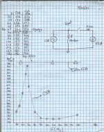
The left picture shows today's results. The right picture shows the results in the previous post. They are from two different experiments, and may look similar casually. The following was done in this experiment on [7/26/21]:
1. Opened Switch as in the simplified schematic of the picture.
2. Determined the woofer's resonance frequency [at 67 Hz] and its Vout [~325].
3. The voltage output of VSA [open switch] was then adjusted with the 25 Ohm pot [schematic in previous post] so as to equal [Vout =325]. This was the experimental variable.The set point of the 25 Ohm pot was left untouched moving forward.
4. CSA only [switch off] generated the characteristic woofer impedance versus frequency graph like was found in the experiment of the previous post.
5. Vout from [CSA +VSA; closed switch] flat-lined to give an average [Vout = 337] in the test frequency range of 50 to 250 Hz.
Analysis.
1. The subjective sound and its level were dominated by VSA. Highly detailed. It was louder than found in the previous experiment. Just compare the performance flat lines [CSA+VSA] in this left picture [~337] versus [135] in the right picture.
2. Subjectively writing, CSA and VSA did not dump power into each other's outputs at the woofer's resonance frequency; equal amplitudes and similar phase. Thus, the conjoined [CSA and VSA] outputs shared equaly the load current. This clearly happened under the watchful eye of VSA; which begs the same question posed yesterday regarding taming woofer distortion!
3. This compound amp did not oscillate; though it embodies some positive feedback; because VSA dumps power into OPT [in schematic] thru the 50-150 Hz. test range and beyond. This injected power is recycled back to the input of VSA via OST.
4. The sound of [CSA +VSA] from the Right and Left experiments were radically different. Imagine the broad range of choice subjective sound which is possible by simply changing the set point of the 25 Ohm pot shown in the schematic of the prototype.
The fun games I play with amps!
Best wishes
Anton
Attachments

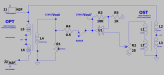
Simpler compound CSA and VSA amp.
I simplified the schematic of the compound prototype amp. The left schematic shows the new one understudy. Compare the older one on the right side of the view. Here's how and why it works; data forthcoming:
1. Gone is OST and its support components. The same input signal from the generator now goes to the front end of CSA [the precision rectifier] and simultaneously to VSA.
2. It works because: 1). The to-be-conjoined output signals from CSA and VSA are in-phase. And 2). The voltage gain of CSA in an 8 Ohm load [switch open] is ~ roughly less than one half that of VSA. The 10 K pot easily controls the output power for VSA, and mix ratios .
3. Works in bullet 2 means it is stable, doe not oscillate and its performance is easily controlled.
My advisor in College at U of I [Dr. Drago; RIP] wrote in his book I bought. "Stir up the pot" wherever you go; prudently of course. Here is the "stir fry". The left side side of either schematic is shown to be "Class aP". I say it may equally be the power output stage of a vacuum tube power amp. That was and is still my DIY intention, and its stated objectives in an earlier post.
Best wishes.
Anton
Attachments

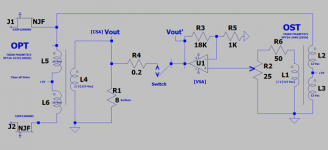
A simpler CSA and VSA compound amp.
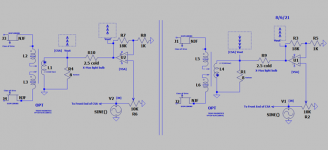
The phase of CSA's power output relative to that of VSA has been on my mind. I have advocated [or alleged] the output of the two power amps to be in phase. Phase alignments across the audio spectrum in not assured; but one may idealize this [perfect] alignment of phase as a tool for analysis and its subjective influence on performance.
The attached schematic is a dual.
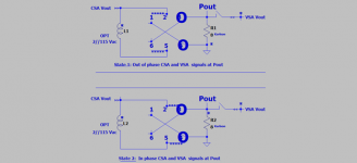
1. The left schematic has been shown in the past post, and others like it prior. It suggests the phase alignment of the amps' power outputs. Note the phase star on L1, and the upward arrows enclosed in rectangles to suggest such a phase alignment of the output signals.
2. Note the phase star on L4 for the right schematic. The phase of CSA's output is opposite to that of L1 in the left schematic. The enclosed [in rectangles] phase arrows due to CSA and VSA are 180 degrees out of phase [idealized].
3. The light bulb joining both amps is a visual diagnostic tool for noting phase alignment. Play music:
3a. The bulb does not light up in the prototype of the left schematic. Because of a minimal voltage drop across it due to phase alignment of the output volatges. The amp plays normally.
3b. The bulb lights up, dims as it follows music peaks in the prototype of the right schematic. Because of a substantial voltage drop across it. As the bulb lights and fades so does the sound pressure out of the Karlson. This is an indication CSA is dumping current into the output of VSA.
4. The light bulb was removed and the power outputs of CSA and VSA were shorted. I need to collect additional observations; but both prototypes sounded different. I'll use a mechanical relay set up to flip the output leads of CSA on the fly to firm up subjective effects.
The value [versus circuit complexity] to the sonics by this "current dumping" is on my table for added study.
Best
Anton
The phase of CSA's power output relative to that of VSA has been on my mind. I have advocated [or alleged] the output of the two power amps to be in phase. Phase alignments across the audio spectrum in not assured; but one may idealize this [perfect] alignment of phase as a tool for analysis and its subjective influence on performance.
The attached schematic is a dual.
1. The left schematic has been shown in the past post, and others like it prior. It suggests the phase alignment of the amps' power outputs. Note the phase star on L1, and the upward arrows enclosed in rectangles to suggest such a phase alignment of the output signals.
2. Note the phase star on L4 for the right schematic. The phase of CSA's output is opposite to that of L1 in the left schematic. The enclosed [in rectangles] phase arrows due to CSA and VSA are 180 degrees out of phase [idealized].
3. The light bulb joining both amps is a visual diagnostic tool for noting phase alignment. Play music:
3a. The bulb does not light up in the prototype of the left schematic. Because of a minimal voltage drop across it due to phase alignment of the output volatges. The amp plays normally.
3b. The bulb lights up, dims as it follows music peaks in the prototype of the right schematic. Because of a substantial voltage drop across it. As the bulb lights and fades so does the sound pressure out of the Karlson. This is an indication CSA is dumping current into the output of VSA.
4. The light bulb was removed and the power outputs of CSA and VSA were shorted. I need to collect additional observations; but both prototypes sounded different. I'll use a mechanical relay set up to flip the output leads of CSA on the fly to firm up subjective effects.
The value [versus circuit complexity] to the sonics by this "current dumping" is on my table for added study.
Best
Anton
Attachments
I assembled this mechanical relay setup a while ago to hear the subjective difference attributed to the phase [positive and negative] of H2. Mr. Pass wrote in his articles on H2 to simply flip the polarity of the loudspeaker so as to unravel this subjective outcome. This idea had prior roots from a YouYube interview of Mr. Pass. He showed in passing a setup with two mechanical relays; me thinking he used it to do an instantaneous A/B blind subjective performance comparisons.
This relay setup performs as suggested by the articles of Mr. Pass. It is used in the current study to switch the phase of B] CSA's output signals [ONLY][/B] on the fly for my blind A/B hearing assessment.
The attached schematic shows the two states of the relay; enabled by remotely turning On/Off power to its energizing coil. A long wire in my hand is terminated by a simple on/off switch so as to apply the 24 VDC output of the PSU's to the relay coil. I sit at the listening location flipping the remote hand switch!
1. The relay flips the phase of CSA's output signal and directs it to the relay's output posts # 3 and 4. This is the same as flipping or moving the ends of the coil put on posts 2 and 5.
2. The setup safeguards shorting the output of VSA. Ground or common is not and should not be switched.
I hope this schematic shows the following sole variable understudy. There's a consequent sonic difference.
State 1 shows Pout emanating from joining the out of phase output signals of CSA and VSA.
State 2 shows Pout emanating from joining the in phase output signals of CSA and VSA.
To be continued for more details..
Best wishes
Anton
Attachments
Music via Class aP amplification is prone to contain H2. It is the nature of this beast! The parent signal [say sinusoidal] is first dissociated at its zero crossing into two pulses, each pulse is DC amplified separately, and finally both pulses are reconstituted to generate a copy of the parent. This resultant signal copy most probably has the relative amplitude of its; say positive-going signal higher or lower in magnitude that in the input parent. This is my understanding of H2's practical outcome as defined by Mr. Pass. On a separtate note, it is great news to see DIYers continue to seek the H2 circuit/kit by Mr. Pass per the posts flooding his H2 thread. They are in for a hearing/musical treat!
The attached schematic is for the prototype understudy. I worked it first as follows to unravel the presense of H2:
1. Open switch connecting VSA to CSA.
2. Class aP CSA is the sole amp playing music thru Karlson.
3. Flip the relay contacts remotely as I described in the past post.
4. The presence of H2 comes thru as described in the articles of Mr. Pass. The phase of H2 makes different music.
Good news! But H2 is another surprise variable. It is independent of the intended study variable which is the subjective sonic effect due to shorting the outputs of CSA with VSA; in phase or out of phase.
To be continued.
Best wishes
Anton
Attachments
Last edited:
- Home
- Amplifiers
- Pass Labs
- Class aP amplification