I previously built an F5 using Christian Viller’s F5c V2.0 boards. In that amp, the JFETs were cascoded, there were 4 MOSFETs per channel, and I had 30 V rails under load. The amplifier sounded wonderful (and still does). However, a friend asked that I construct him an amplifier for a relatively large room, mainly for listening to classical music with electrostatic speakers of average efficiency.
Christian was kind enough to update his boards to include P3 and resistors on the bases of the cascoding transistors, and I acquired some of them (and have sent a few to some diy members who have requested them).
I decided to aim for 40 V rails using these new boards, and to build a dual mono amp (one power line in, two transformers, two PS boards). Christian, 6L6, and others have been extremely helpful in getting this thing built. I thought I would provide some documentation of the build for new amp-and rather inexperienced builders like I am. Each build brings new mistakes and great lessons.
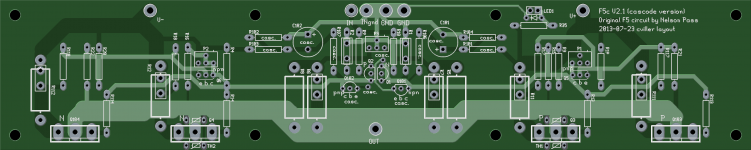
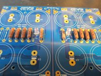
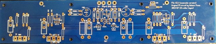
First, here is a photo of Christian’s V2.1 board along with a modified schematic I used. I did not include a current limiting protection circuit. I had matched Toshiba JFETs (from Spencer) and matched Fairchild MOSFETs left over from previous builds. For source resistors on the MOSFETs, I had some 1 ohm 5 W non-inductive resistors I needed to use, so the schematic showing 0.5 ohm 10W at these locations simply represents my use of two components in parallel.
Late edit: Those 220 ohm feedback resistors in the schematic are supposed to be labeled R5, R6, R7 and R8. Sorry for the confusion.
IMPORTANT. For builders, be sure to read from comment 120 to the end. I found evidence of parasitic oscillation and added 1 nF film compensation caps.
Christian was kind enough to update his boards to include P3 and resistors on the bases of the cascoding transistors, and I acquired some of them (and have sent a few to some diy members who have requested them).
I decided to aim for 40 V rails using these new boards, and to build a dual mono amp (one power line in, two transformers, two PS boards). Christian, 6L6, and others have been extremely helpful in getting this thing built. I thought I would provide some documentation of the build for new amp-and rather inexperienced builders like I am. Each build brings new mistakes and great lessons.
First, here is a photo of Christian’s V2.1 board along with a modified schematic I used. I did not include a current limiting protection circuit. I had matched Toshiba JFETs (from Spencer) and matched Fairchild MOSFETs left over from previous builds. For source resistors on the MOSFETs, I had some 1 ohm 5 W non-inductive resistors I needed to use, so the schematic showing 0.5 ohm 10W at these locations simply represents my use of two components in parallel.
Late edit: Those 220 ohm feedback resistors in the schematic are supposed to be labeled R5, R6, R7 and R8. Sorry for the confusion.
IMPORTANT. For builders, be sure to read from comment 120 to the end. I found evidence of parasitic oscillation and added 1 nF film compensation caps.
Attachments
Last edited:
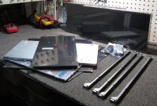
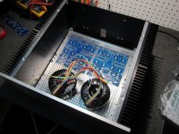
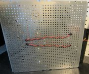
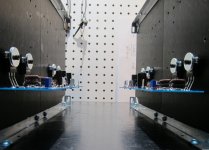
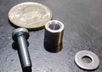
I chose to use the 5U chassis from the store along with their hardware for the back panel. I wanted the extra room for dual power supplies and also really needed the heat sink capacity, given the increased power out with 40 V rails. I assembled the chassis to see how everything fit, and based on a suggestion from ZM, I chose to place spacers on the perforated base panel so I could run wires beneath. I picked up various sized spacers and some longer hardware at a local store. In the photos, immediately below, I show ¼ inch nylon spacers, but I ended up using ½ inch spacers during final assembly to get the clearance I needed for wiring. The amp board test-fitted perfectly – no need for any additional drilling or tapping.
Attachments
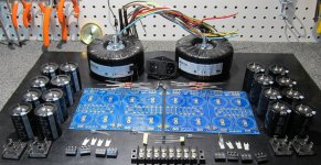
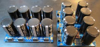
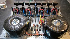
I have used Piltron transformers before and had been pleased with them. I ordered their product # 757017201. Each of the two toroidal transformers was rated at 400 VA, had 2 primaries and two secondaries, with secondaries of 30 VAC. I know 400 VA for a single board was overkill, but it did not cost much more to pick up the extra power, and I wanted to decrease chances of hum/vibration from a transformer being on the edge, so to speak.
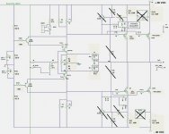
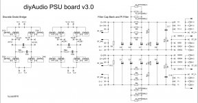
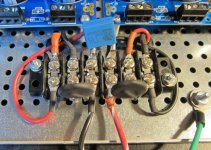
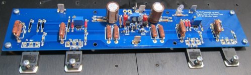
For the PSs, I chose to use the most recent PS boards from the store (v3.0) and have attached a schematic of those boards. I wanted a straight-forward CRC and did not use C17 or R12 on the schematic.
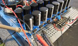
I picked up Panasonic 22,000 uF, 50 V caps (Mouser part # 667-ECO-S1HP223EA), 8 caps per PS board. And I used 0.47 ohm 5 W power resistors for the CRC, also 8 per board. I had a bunch of these to use for something and they happened to be non-inductive, which they did not need to be for this purpose. The power switch takes 20 mm fuses. Of course, CL-60s for inrush protection.
I had plenty of bridge rectifiers (200 V, 35A, digikey GBPC3502A-ND). Because I used bridge rectifiers, I broke off and didn’t use the diode sections from the PS boards. Of course, the boards were designed specifically so the diode sections could be easily separated.
2.2K ohm 5 W bleeder resistors (R19). (I had 5 watt resistors lying around to use for something, but they don’t need to be this large).
I chose blue LEDs at 6L6’s suggestion (digikey C503B-BCS-CV0Z0461-ND), and used 22K ohm resistors in series with the LEDs. I also decided to use the blade connectors and the Euro connectors for connections to and from the boards.
For the PSs, I chose to use the most recent PS boards from the store (v3.0) and have attached a schematic of those boards. I wanted a straight-forward CRC and did not use C17 or R12 on the schematic.
I picked up Panasonic 22,000 uF, 50 V caps (Mouser part # 667-ECO-S1HP223EA), 8 caps per PS board. And I used 0.47 ohm 5 W power resistors for the CRC, also 8 per board. I had a bunch of these to use for something and they happened to be non-inductive, which they did not need to be for this purpose. The power switch takes 20 mm fuses. Of course, CL-60s for inrush protection.
I had plenty of bridge rectifiers (200 V, 35A, digikey GBPC3502A-ND). Because I used bridge rectifiers, I broke off and didn’t use the diode sections from the PS boards. Of course, the boards were designed specifically so the diode sections could be easily separated.
2.2K ohm 5 W bleeder resistors (R19). (I had 5 watt resistors lying around to use for something, but they don’t need to be this large).
I chose blue LEDs at 6L6’s suggestion (digikey C503B-BCS-CV0Z0461-ND), and used 22K ohm resistors in series with the LEDs. I also decided to use the blade connectors and the Euro connectors for connections to and from the boards.
Attachments
Power resistors were mounted slightly elevated off the boards. Made sure to connect grounds between both sides of each board. I used #18 solid at four locations for ground connections. Then added spades, Euro connectors and caps.
I drilled some holes for wire runs below the base and inserted grommets. Also mounted terminal strips in the back and front. I needed to bring power in the back to a terminal strip where the CL-60s would be incorporated, and then take that power under the bottom panel to the front of the amplifier where the transformers would be mounted. I mounted the bridge rectifiers using thermal paste (no insulation needed), but don’t know that I needed it. Drilled holes for the transformer bolts. I used nylon spacers on the PS boards. Used 16 gauge stranded for runs from the back terminal strip to the transformers and to and from diodes. Connected ground from each PS boards to chassis through a CL-60. That is, each board when through its own CL-60 to ground.
I drilled some holes for wire runs below the base and inserted grommets. Also mounted terminal strips in the back and front. I needed to bring power in the back to a terminal strip where the CL-60s would be incorporated, and then take that power under the bottom panel to the front of the amplifier where the transformers would be mounted. I mounted the bridge rectifiers using thermal paste (no insulation needed), but don’t know that I needed it. Drilled holes for the transformer bolts. I used nylon spacers on the PS boards. Used 16 gauge stranded for runs from the back terminal strip to the transformers and to and from diodes. Connected ground from each PS boards to chassis through a CL-60. That is, each board when through its own CL-60 to ground.
Attachments
If I may, where did you get those boards from?
Hi. Drop me a PM if you are interested in picking up a couple. I think I have the only boards at present.
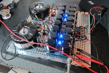
Mounted hardware on the back panel and placed some slow-blow 2 A fuses. Powered up using a 100 W light bulb. The bulb lit brightly and did not dim. I had the primaries wired incorrectly. A good reason to always power up with a bulb. I have a variac, but still prefer the bulb because of the obvious signal it gives when too much current is flowing.
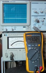
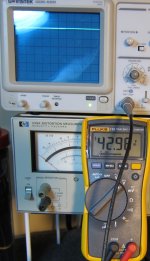
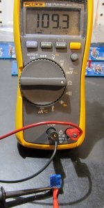
The wiring in the previous photos was correct. I didn’t show photos of the incorrect wiring since I didn’t want to cause confusion for those who didn’t read on. I spoke with 6L6 who knew what the problem was almost without completing the sentence. Simply switched the position of two primary leads and everything was fine. A brief brightness to the bulb as caps charged, and then the bulb went out, appropriately. I removed the light bulb from the circuit and took some measurements. I have shown a couple photos of readings from one board. -43.02 on the negative rail and 42.96 on the positive rail. No ripple to speak of on the scope, but this will change when the PS is loaded.
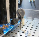
I received a PM asking how the CL-60 was connected from a board to chassis ground, so I included a photo that shows this in more detail.
The wiring in the previous photos was correct. I didn’t show photos of the incorrect wiring since I didn’t want to cause confusion for those who didn’t read on. I spoke with 6L6 who knew what the problem was almost without completing the sentence. Simply switched the position of two primary leads and everything was fine. A brief brightness to the bulb as caps charged, and then the bulb went out, appropriately. I removed the light bulb from the circuit and took some measurements. I have shown a couple photos of readings from one board. -43.02 on the negative rail and 42.96 on the positive rail. No ripple to speak of on the scope, but this will change when the PS is loaded.
I received a PM asking how the CL-60 was connected from a board to chassis ground, so I included a photo that shows this in more detail.
Attachments
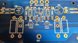
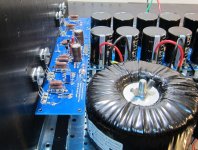
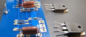
I have again shown the F5 boards I am using along with a close-up of the center. In the close-up you can see the additions of P3 and of R106 and R107 to the bases of cascoding transistors Q101 and Q102. As on the previous version of this board, the drains of JFETs Q1 and Q2 and diverted into the holes labeled “casc.” if cascoding is used, as it was in this build.
As I mentioned earlier, I had some non-inductive 5W 1R resistors (1%), and I used two in parallel for source resistors on the MOSFETs. R1 and R2 were 10R 1W 1% metal film resistors and had to be mounted soldier style. I had some 220 ohm 5W 1% non-inductive resistors I chose to use as feedback resistors (R5-8). I just noticed on the schematic on post #1 that “R108” did not get removed below R6. That R108 label should be ignored. For R10, I had 100 K ohm resistors that I soldered in parallel to provide for 50k ohms. I used the same blue LEDs as were used in the PS boards. P3 was digi-key part # 3296W-201LF-ND
In the 4th photo you can see how the drains from the JFETs are placed in the “casc.” holes.
Before mounting P3, I used an ohm meter to adjust it to the very center of its range, with equal resistance from center tap to both sides.
Attachments

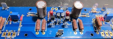

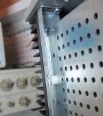
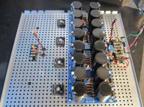
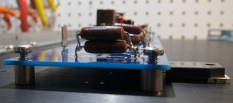
I soldered MOSFETs to the boards, planning to suspend the boards by the MOSFETs horizontally. Though the heat sinks are drilled to mount the boards to the sinks using spacers, I prefered horizontal placement simply for the ease of adjusting bias with P1 and P2 with the top of the chassis off. Take a look at the 3rd and 4th photos, in which I had loosely mounted the MOSFETs to the sinks to see what it would look like. I am sure that most all of you immediately see the problem that was not obvious to me.
(Christian - great to hear from you. I have received great feedback on your boards, and as you can see, I am finally getting around to using them, myself.)
(Christian - great to hear from you. I have received great feedback on your boards, and as you can see, I am finally getting around to using them, myself.)
Attachments
I soldered MOSFETs to the boards, planning to suspend the boards by the MOSFETs horizontally.........
nono
you must suspend pcbs separately
nono
you must suspend pcbs separately
And why is that, ZM?
(There is yet another problem in this horizontal suspension.)


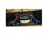
Thanks for the insight regarding suspending boards that can get both heavy and hot. Having one of those droop down and shorting out on the sink or elsewhere would not be desirable. I have attached a photo of a previous build where I used horizontally mounted boards but suspended them from below, as they should be in that situation.
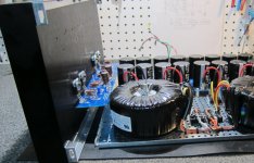
As I said at the beginning, I make new errors and learn new things with each build. In addition to ZMs important point about how wrong it is to suspend a board from MOSFETs by themselves, the other problem I had not anticipated was that when sitting horizontally, the boards hit the transformers and PS caps, preventing the chassis from fitting together (pictures below). This would not have been an issue with a single transformer and single PS board, but certainly was with dual mono construction.
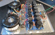
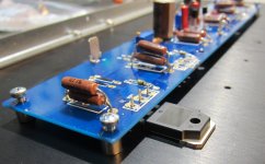
Lesson learned. 6L6 prodded me to simply mount them as designed, which is what I should have done to begin with. MOSFET leads were clipped close to the boards. After using copper braid to clean up the boards (about 20 minutes), I could easily use these same MOSFETs with the boards mounted correctly on the heat sink with aluminum spacers. The last photo shows the board and MOSFETs loosely secured to the sink prior to soldering them into place.
As I said at the beginning, I make new errors and learn new things with each build. In addition to ZMs important point about how wrong it is to suspend a board from MOSFETs by themselves, the other problem I had not anticipated was that when sitting horizontally, the boards hit the transformers and PS caps, preventing the chassis from fitting together (pictures below). This would not have been an issue with a single transformer and single PS board, but certainly was with dual mono construction.
Lesson learned. 6L6 prodded me to simply mount them as designed, which is what I should have done to begin with. MOSFET leads were clipped close to the boards. After using copper braid to clean up the boards (about 20 minutes), I could easily use these same MOSFETs with the boards mounted correctly on the heat sink with aluminum spacers. The last photo shows the board and MOSFETs loosely secured to the sink prior to soldering them into place.
Attachments
To make it easier to reach the posts and optimise the mosfet placement on the sink, I normally mount them upside down (with mosfets in the bottom).
Hi. I don't understand exactly what you mean by your statement that you mount "them upside down (with mosfets in the bottom)." Might you explain a bit or provide a quick photo or sketch?
Thanks.
- Status
- This old topic is closed. If you want to reopen this topic, contact a moderator using the "Report Post" button.
- Home
- Amplifiers
- Pass Labs
- F5c (cascode) cviller boards 40 V rails build