
Nah, just flip the main breaker before you turn in. Turns off the lights, *and* prevents risk of electrical fire ")
-
Ok, so, I’ve got a Focusrite Scarlet which I’m feeding from the output of my Front End. Amp is unloaded, taking a 1 KHz tone.
I’ve got the 2nd and 3rd harmonic clear as day in REW, and using the distortion products window to see what’s going on. I can adjust P3 and make the harmonics go up and down, so far so good. But when I try to balance the bias currents across Q3 and Q4c it totally changes the harmonics! It’s like I can set them with P3 *or* bias, but to make harmonics what I want means I can’t have balanced bias.
Does this make sense?
Very good now you have the proper tools.
- Let the amp warm up for an hour or so
- With P3 you can adjust H2.
- P3 will also change Bias and Offset.
So you adjust P3 for minimum H2 then readjust Bias and Offset via P1 and P2.This will change the harmonics again so thats normal.
- Then readjust P3 again for minimum and so forth.
You cannot get any thd spectra you want, but you can trade off H2 for a little more H3. Or you can maximize H2 for a little less H3, if you like. Bias current through Q3 and Q4 should be the same.
Don´t know if thats coherent with theory but I found cancelling H2 gives a little more H3.
Last edited:
It matters in as much as it has an effect. Turn P3, and the voltages across (current through) R3 and R4 change. See the schematic.
Maybe I'm not interpreting your question properly.
re: what ozorfis said, I found that the total bias of the BA-3 FE could affect THD along with the relative balance of H2 and H3. You can measure it with or without the output stage. See the BA-3 as a pre-amp thread.
I found that changing P3 changes the amount of H2 relative to H3 along with THD if bias is kept constant and DC offset (for the FE before the cap) is reset to as close to null as practical. If you just twiddle with P3 w/o resetting the bias and offset, then results are likely unpredictable / not repeatable.
I did all this before I knew how to check the relative phase of H2 to the fundamental, so apologies for not knowing which way things go. I can't wait to try it though.
When I changed P3, I measured and tracked voltage drops across R3, R4, R10, and R11. That way, I can go back to any previous point reliably (I think).
---------------------------------------------
Ozorfis, when you reduced H2 were you doing it balanced (my guess is that was easier to completely null)?
AND/OR, did you just get it to where H3 was higher than H2 (H3 goes up a wee bit, but mostly reduced H2) with a single-ended amp? With my SE amp, I could not get H2 into the noise floor, but I could get it pretty low relative to H3. Initially, I had it set for months and months with H2 and H3 roughly equal.
My guess... is that there could be more control over the relative levels of H2 and H3 along with THD in the balanced amps, but that's just theory. I'm still playing vs. knowing. My guess is that it's also now a 6 pot balancing act vs. 3 for each channel. So... yikes.
I'm still not quite ready to dedicate my other 4U/500 and the sweat, but I really, really want to do it. It's absolutely insane overkill, but All the boards are stuffed, but I need to swap in the Toshiba parts for Q3/Q4 and put in the DIP switches for the FE. Then, I'd have to re-set everything again. The existing amp sounded sooooo good. Going balanced has been one of my long-neglected projects.
I also found that for me, twiddling P3 had more of a measurable and more of a perceived audible effect than any reasonable changes that I made in the bias of the output stage. But again, I'm operating on 24V rails based around a 4ohm load. People running ~32V rails may have differing results.
Fun, fun stuff!
As always... more skilled minds, please chime in.
Edited to add - Since I did the amp in two "phases" (pardon the pun) starting with 3 pair and then to the 6 pair... It should be noted that (to me) moving to double the output devices had a noticeable effect (to me) re: bass control. That's separate from playing with the output stage bias current and FE knobs.
Maybe I'm not interpreting your question properly.
re: what ozorfis said, I found that the total bias of the BA-3 FE could affect THD along with the relative balance of H2 and H3. You can measure it with or without the output stage. See the BA-3 as a pre-amp thread.
I found that changing P3 changes the amount of H2 relative to H3 along with THD if bias is kept constant and DC offset (for the FE before the cap) is reset to as close to null as practical. If you just twiddle with P3 w/o resetting the bias and offset, then results are likely unpredictable / not repeatable.
I did all this before I knew how to check the relative phase of H2 to the fundamental, so apologies for not knowing which way things go. I can't wait to try it though.
When I changed P3, I measured and tracked voltage drops across R3, R4, R10, and R11. That way, I can go back to any previous point reliably (I think).
---------------------------------------------
Ozorfis, when you reduced H2 were you doing it balanced (my guess is that was easier to completely null)?
AND/OR, did you just get it to where H3 was higher than H2 (H3 goes up a wee bit, but mostly reduced H2) with a single-ended amp? With my SE amp, I could not get H2 into the noise floor, but I could get it pretty low relative to H3. Initially, I had it set for months and months with H2 and H3 roughly equal.
My guess... is that there could be more control over the relative levels of H2 and H3 along with THD in the balanced amps, but that's just theory. I'm still playing vs. knowing. My guess is that it's also now a 6 pot balancing act vs. 3 for each channel. So... yikes.
I'm still not quite ready to dedicate my other 4U/500 and the sweat, but I really, really want to do it. It's absolutely insane overkill, but
All the boards are stuffed, but I need to swap in the Toshiba parts for Q3/Q4 and put in the DIP switches for the FE. Then, I'd have to re-set everything again. The existing amp sounded sooooo good. Going balanced has been one of my long-neglected projects. I also found that for me, twiddling P3 had more of a measurable and more of a perceived audible effect than any reasonable changes that I made in the bias of the output stage. But again, I'm operating on 24V rails based around a 4ohm load. People running ~32V rails may have differing results.
Fun, fun stuff!
As always... more skilled minds, please chime in.
Edited to add - Since I did the amp in two "phases" (pardon the pun) starting with 3 pair and then to the 6 pair... It should be noted that (to me) moving to double the output devices had a noticeable effect (to me) re: bass control. That's separate from playing with the output stage bias current and FE knobs.
Last edited:
Does the position of P3 relative to the voltage across R3 and R4 matter? Papa mentions the degree of H2 going more positive as P3 aims towards Q1 and more negative as P3 aims toward Q2.
Papa is referring to the phase of H2 being positive or negative. Starting from the position of P3, where H2 is minimal, you get more positive phase H2 by turning P3 one way and more negative phase H2 by turning the other way.
The phase of H2 I could not see with a soundcard. Here I had to use a notch filter and a scope, which was only of educational value.
Ozorfis, when you reduced H2 were you doing it balanced (my guess is that was easier to completely null)?
.
I adjusted each channel in single ended mode. Not sure if it is possible to do in balanced operation simultaneously.
Front end balanced is a little less distortion but comparable. With P3 you can still have H2 balanced, if desired. I am running minimum H2 now as I have become a sucker for detail.
Output stage balanced with in my case IR IRFP9240 is much less H2 -like Papa said. I still have to change to Harris parts. Got them matched already but like you haven´t found the vigor yet to completely disassemble those wonderful sounding amps.
Yes I strongly second Toshibas for the front end. Going balanced you get even more bass control and more detail. Initially I liked the amp SE better, as it got rid of some digital harshness from my DAC. I then switched my DAC from RME to Denafrips R2R and now enjoy detail without harshness.
^ Thanks for sharing your continued impressions and your path.
Ugh... you bring up one thing that I continue to ignore (consciously)... the vast majority of my amps are built with Vishay parts in the output stage. I haven't the heart to swap out the Vishay parts for Harris parts. I did the same perhaps... I bought a metric crap-ton (that's just over 100 pieces) of Vishay N and P channel parts and matched them all up meticulously. That's before I realized that all parts with the same part number are not created equal. So, I bought a bunch of Harris parts, just to ... have. I chalk it up to learning.
Ugh... you bring up one thing that I continue to ignore (consciously)... the vast majority of my amps are built with Vishay parts in the output stage. I haven't the heart to swap out the Vishay parts for Harris parts. I did the same perhaps... I bought a metric crap-ton (that's just over 100 pieces) of Vishay N and P channel parts and matched them all up meticulously. That's before I realized that all parts with the same part number are not created equal. So, I bought a bunch of Harris parts, just to ... have. I chalk it up to learning.
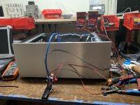
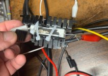
Sorry for the double post, but I wanted to show off a little invention I whipped up.
I got tired of moving my meter clips around all the time playing with harmonics and bias levels, so I made a simple data interface for my front end. Each Cat5 jack is connected to a subset of test points: MOSFET bias resistors, top of C3, D out, and ground, for each channel, and then R3/R4 for both channels. The output is wired to a terminal block that I can hook clips too. The wiring is consistent so I can swap the plug between jacks and my meters maintain useful values.
I got tired of moving my meter clips around all the time playing with harmonics and bias levels, so I made a simple data interface for my front end. Each Cat5 jack is connected to a subset of test points: MOSFET bias resistors, top of C3, D out, and ground, for each channel, and then R3/R4 for both channels. The output is wired to a terminal block that I can hook clips too. The wiring is consistent so I can swap the plug between jacks and my meters maintain useful values.
Attachments
No issue with Harris. May be an issue with Vishay / IR, particularly P-channel parts.
I am only going by notes and things I have read. I cannot claim to understand it, and I may be well off-base. I've never modeled the parts myself.
With that said... I have pasted in my notes from 'somewhere' that IR (Vishay may have the same issue) IRFP9240s have a "known" and documented transconductance issue in the midrange frequencies. So, Harris parts may be 'better'. Based on that... I bought some Harris parts before they too become unobtainium. I may have made a foolish choice.
Again... don't rely on this numbskull. Wait for others to confirm or write me off as yet another person that can't seem to put proper footnotes in their own build notes to cite where I got this nonsense. I rely on the intelligence of others, and I try to maintain decent notes.
Wish I could find the exact sources. Sorry ... brain fried at the moment.
Edited to add - Didn't want to add another entire post. I didn't see your second post until after I posted mine. Super cool add-on!!!!!
Last edited:

Thank you, Dennis. Notes updated with proper citations and links.
Thanks for everyone's patience. I didn't want to mislead, and I have to mock myself for not including a proper citation when the knowledge is not my own.
There are two other locations where I must have grabbed quotes. A better search led me straight back.
1) Nelson providing some context here (along with some backstory further up the thread) in post #8
https://www.diyaudio.com/forums/pas...arris-intersil-9240-genealogy.html#post515088
2) I also read it here in the F4 thread, which is where I must have gotten the chunk I referenced earlier.
First note I had was a question asked by Vunce (didn't have an answer in my notes) in post 1572
https://www.diyaudio.com/forums/pas...ilding-pass-f4-amplifier-158.html#post5994347
Later on Rodeodave (which is where I had paraphrased his words into my notes) said this in post 2042.
https://www.diyaudio.com/forums/pas...ilding-pass-f4-amplifier-205.html#post6281541
That reference likely comes from Page 9 of this...which Dennis kindly pointed me back to.
https://firstwatt.com/pdf/art_mos_test.pdf
Sheesh... I need a better memory and to take better care of my notes.

Thanks again!
Thanks for everyone's patience. I didn't want to mislead, and I have to mock myself for not including a proper citation when the knowledge is not my own.
There are two other locations where I must have grabbed quotes. A better search led me straight back.
1) Nelson providing some context here (along with some backstory further up the thread) in post #8
https://www.diyaudio.com/forums/pas...arris-intersil-9240-genealogy.html#post515088
2) I also read it here in the F4 thread, which is where I must have gotten the chunk I referenced earlier.
First note I had was a question asked by Vunce (didn't have an answer in my notes) in post 1572
https://www.diyaudio.com/forums/pas...ilding-pass-f4-amplifier-158.html#post5994347
Later on Rodeodave (which is where I had paraphrased his words into my notes) said this in post 2042.
https://www.diyaudio.com/forums/pas...ilding-pass-f4-amplifier-205.html#post6281541
That reference likely comes from Page 9 of this...which Dennis kindly pointed me back to.
https://firstwatt.com/pdf/art_mos_test.pdf
Sheesh... I need a better memory and to take better care of my notes.
Thanks again!
How do you like your Iron Pre, Russel?
One of my best, it will be popular.
Russellc
Well, I've been continuing to experiment with my pots and my harmonicas. The more I learn the less I know. Up is down, black is white, and everything changes when I look at it. On the plus side, it's playing Red Hot Chili Peppers right now and sounds pretty damn good. I'll keep wandering around out here for a while. I'll send up a harmonic or two if I need help.
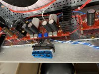
Here's a picture for your trouble. Y'all told me to put heatsinks on my resistors, so I did.
Here's a picture for your trouble. Y'all told me to put heatsinks on my resistors, so I did.
Attachments
Here's a picture for your trouble. Y'all told me to put heatsinks on my resistors, so I did.
This looks awkward (big gaps and no heat-transfer-stuff aka goop/mica/keratherm/… ?).
I‘d suggest to redo it, making sure that there‘s really zero gaps between heatsink and resistor…
- Home
- Amplifiers
- Pass Labs
- BA-3 Amplifier illustrated build guide