6L6 said:Speaker negative (-) is from the PSU GND.
Is there a reason to connect this to PSU ground instead of directly to the star ground?
Yes, many reasons. Most important: star ground/chassis ground is NOT the same as audio ground. Have you seen the thermistor between audio gnd and chassis gnd in the schematic? It provides resistance between the two iot avoid ground loops. If a fault occurs and the thermistor warms up, it let’s it «all» out straight to chassis/star gnd. But during normal operation, the two are basically isolated from each other.
Thats not to say it might be quiet connected to star gnd as well, it’s just not recommended")
Thats not to say it might be quiet connected to star gnd as well, it’s just not recommended
Last edited:
Wait for others to comment but I would say yes. I can't explain why, but the PS is usually grounded to that point through a CL-60. Just seems odd to connect something that would normally be on the PS board directly to that star. I could be dead wrong, but it just doesnt look right, wise to ask.
Looks like andy got there. I figure, they put the pad here and they know more than me so "I will do as Simon (usually 6l6 or Zenmod) says." Works for me.
Russellc
Looks like andy got there. I figure, they put the pad here and they know more than me so "I will do as Simon (usually 6l6 or Zenmod) says." Works for me.
Russellc
Last edited:
Without the CL-60 star and PSU/audio gnd would be basically at the same or so potential. With the CL-60, you get protection from ground loops=wise. If you look up the BA-2 output stage manual, all the info should be there. Those are the basics. I agree with Russel: Nelson says do it to avoid gnd loops (not fun!), and everyone follows suit. So just do it 
Edit: sorry, blank head, you were ahead, Yes, the PSU schem in the BA-2 manual
Edit: sorry, blank head, you were ahead, Yes, the PSU schem in the BA-2 manual
Last edited:
While I'm asking silly questions: I routed the output ground to the front end board ground by mistake. Since it grounds to the same place as the input ground, can I just add a wire to the PSU ground? (doubling-up one of the front-end ground connections).
EDIT: Also, I apparently forgot to order the CL-60's. Can I stick a 10k resistor in there for testing and adjustment?
EDIT: Also, I apparently forgot to order the CL-60's. Can I stick a 10k resistor in there for testing and adjustment?
Last edited:
The front end boards have tiny holes. For speaker returns, being high current, I would not recommend you route that to the FE board in this instance. Use minimum 16awg. Meaning: desolder that gnd wire from speaker post and route to PSU instead. Then solder a thicker wire to the speaker post, connecting it to psu aftwerwards.
10k is too high. Just stick a wire 12-18awg between psu and star. If it hums, try disconnecting, and you found a potential use for the CL-60 but don’t disconnect that wire unless sure the circuit works. Meaning stable DC offset and no overheating components.
Wire won’t kill anything. But 10k might hinder a circuit fault reaching the chassis. Before it is too late.
Regards,
Andy
10k is too high. Just stick a wire 12-18awg between psu and star. If it hums, try disconnecting, and you found a potential use for the CL-60
but don’t disconnect that wire unless sure the circuit works. Meaning stable DC offset and no overheating components.Wire won’t kill anything. But 10k might hinder a circuit fault reaching the chassis. Before it is too late.
Regards,
Andy
Would a lower value resistor be useful?
I'll adjust my wiring and post a pic. I'm actually at a stage where it's mostly all in place and a review by someone more experienced would be very helpful
I'm using 18 awg from the output board to the speakers, should I double that up to 16 awg, too?
I'll adjust my wiring and post a pic. I'm actually at a stage where it's mostly all in place and a review by someone more experienced would be very helpful
I'm using 18 awg from the output board to the speakers, should I double that up to 16 awg, too?
I would not use a resistor in a power amp, unless a big one (many watts). Someone else would have to tell how big.
If only for testing, a wire is just fine. No risk that way. You are only testing functionality.
Need to go to bed. Good luck! Looking forward to pictures. Just post, many very qualified and helpful people here. The best (me not one of the latter) 
If only for testing, a wire is just fine. No risk that way. You are only testing functionality.
Need to go to bed. Good luck! Looking forward to pictures. Just post, many very qualified and helpful people here. The best
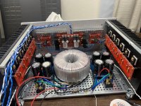
(me not one of the latter) Ok, here's my build, I have yet to attach the back cover, but that's basically it. I'm happy to upload more pics if there are things you want to see.
All wires are 18awg solid core. Blue is signal, white is signal return, red is V+ and Black is V-/ground.
Input wires are twisted together and the pairs bundled and run on the left side to the input board. Speaker output are one pair each, twisted, bundled with the input wires. Transformer is AnTek 6224.
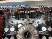
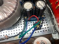
I split the power supplies for space/layout reasons. They are joined by three ground wires, braided, connected above the transformer. V+ comes off the left supply, V- comes off the right. Signal ground from the input board goes to the ground points on the rectifier boards (I split it because why not, symmetry). Speaker grounds come off the same rectifier ground points as a twisted pair each. Power grounds come off the inner ground pins and go to the star ground.
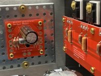
I wired the bridge rectifiers the same for each channel. I hope that's right, because the boards themselves are reversed (I should double check the schematic to confirm). On both boards, + goes to D++ and - goes to D--.
I need to add the thermistors, I forget them in my initial order.
Thoughts, comments, snide remarks, please! My motto is "I have no idea what I'm doing"
All wires are 18awg solid core. Blue is signal, white is signal return, red is V+ and Black is V-/ground.
Input wires are twisted together and the pairs bundled and run on the left side to the input board. Speaker output are one pair each, twisted, bundled with the input wires. Transformer is AnTek 6224.
I split the power supplies for space/layout reasons. They are joined by three ground wires, braided, connected above the transformer. V+ comes off the left supply, V- comes off the right. Signal ground from the input board goes to the ground points on the rectifier boards (I split it because why not, symmetry). Speaker grounds come off the same rectifier ground points as a twisted pair each. Power grounds come off the inner ground pins and go to the star ground.
I wired the bridge rectifiers the same for each channel. I hope that's right, because the boards themselves are reversed (I should double check the schematic to confirm). On both boards, + goes to D++ and - goes to D--.
I need to add the thermistors, I forget them in my initial order.
Thoughts, comments, snide remarks, please! My motto is "I have no idea what I'm doing"
Attachments
- Home
- Amplifiers
- Pass Labs
- BA-3 Amplifier illustrated build guide