One of the N channels on the left sink biases much higher than the others. 30%. ZM says that those three N channels definately have a matching issue. But the store don’t buy it, since, it appears, Papa matched them himself! (!!)
So they asked me to do some tests for which I do not have the equipment, knowledge or time for. So instead I ordered another matched set. But who knows? I now have two transformers, three heatsinks, two sets of boards for BA-3, three sets of MOSFETs (2xBA-3 and one for F5T), and boards for F5t. The future is bright? Or maybe just busy... haha
Three sinks: do you think it is possible to build half an amp?
Last edited:
Hello Andy,
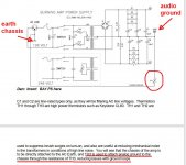
I make my connections the same way like you did - one exception:
I go from mid PSU (0 V = audio ground) over the groundloopbreaker
(35A bridgerectifier+CL60) to IEC-inlet ground/case.
So, my audioground is slightly floating.
I have added a sketch....
Don't ask me if this is the right way???
Greets
Dirk
New fets? I seem to recall something about some fets running cooler than others. Is
that what the replacements are for? (Or are you already planning to build another
amp?)
Most specifically, since the amp if working fine now, the replacements are intended to let me bias high enough to really keep them sinks warm. 200 wata dissipation apprently doesnt overheat them. Some advantages of living in a cold country!
to andynor
Hello Andy,
I had to search a little bit - but there are many articles and pics about groundloopbreakers on the web.....
A good article is on the website of Elliott Sound Products:
Earthing (Grounding) Your Hi-Fi - Tricks and Techniques
Perhaps you know it?
Greets
Dirk
Hello Andy,
I had to search a little bit - but there are many articles and pics about groundloopbreakers on the web.....
A good article is on the website of Elliott Sound Products:
Earthing (Grounding) Your Hi-Fi - Tricks and Techniques
Perhaps you know it?
Greets
Dirk
Good morning, Dirk!
I will check that one out. I am currently reading and rereading Bonsais article on the subject:
http://hifisonix.com/wordpress/wp-content/uploads/2019/02/Ground-Loops.pdf
As I see it, my NTC to chassis does that job for me right now. Mostly, I am just curious on the physics behond the extra rectifier. Maybe try it? =)
However, since my hum does not go away when i connect the amp to an ungrounded outlet, I believe the error is elsewhere, like you expressed might be the case. I am currently thinking it is either a cross channel loop, capacative coupling between secondaries and primaries of the tranny, or a common impedance loop. I will in time try to falsify those hypothesis. But will still explore improving my gnd scheme.
Btw, do you have a Mouser link for those rectifiers you use in your beauty of an amp? My fast rectifiers make quite some noise, so I am hesitant of moving them closer to the PSU and FE.
Regards,
Andy
Last edited:
Hello Andreas,
I'm not an expert in these things, but let’s try to improve it. You will need to do some tests to determine what kind of problem it is.
1. Unplug the amp from the mains and remove any input cables and disconnect from the speakers.
2. Disconnect the thermistor (TH1 in post 605 circuit diagram). Measure from the amplifier 0V and input socket signal ground to the chassis to confirm it is open circuit (use high resistance mode, not diode mode). You should be measuring 100's of k Ohms or higher. If you measure a short or very low Ohms, you will have an earth loop problem in your amp and need to resolve it. Reconnect the thermistor (for safety) after you have fixed it.
3. The next test is for common impedance noise. Make sure the input connector signal grounds are NOT joined together inside the amp. Short each input, connect the speakers and re-apply power. If you hear hum, there is a good chance you have a common impedance coupling problem and this means you should look carefully at how the grounds are connected at the PSU side - I assume since this is Nelson Pass design amp board, there are no problems on the amplifier module side. If you hear no noise (or very low noise), then there is a good chance you do not have a common impedance coupling issue, or that it is not your biggest problem at this stage.
4. If there is no noise in step 3, the next test is for a cross-channel ground loop. In a typical cross channel ground loop, the amplifier is quiet with only one input channel connected, or no inputs connected, but when you connect BOTH input channels, then you get hum. To test for this, take a standard 1 metre phono cable and connect it from one input to the other so it forms a loop outside the amplifier. You should hear no noise on a good amp. If you get hum (but none with the cable disconnected both ends), its likely a cross channel ground loop and it is arising inside your amp due to the transformer mag field intersecting a loop formed by the signal ground connection from the one input, through the module, through the 0V power connection to the PSU, out to the other module via the same route and around the external cable. To overcome/reduce this issue, check you using hum breaking resistors (HBR) - see pages 30-41 in the Ground Loop presentation (link below in my signature) and then check point 5 below.
5. Have you routed the input connector to amplifier module cables correctly? The shortest connection is not always the quietest (See pages 61-64 in the Ground Loop presentation). I usually mount these next to each other not separate on either side of the rear panel (although I did this on my earlier amps). You do this to minimize the loop area between the channels. If you join the grounds together where the connectors come into the amplifier, you trap cross channel ground loops inside the amplifier. If your input connectors are on either side of the rear panel and you are running the input cables directly to each amplifier module, you will be creating a very large cross channel ground loop area and you will not help the situation by joining the grounds together on the input sockets in that case. Only bond the input grounds together if the connectors are located right next to each other.
6. This is a class A amplifier with a heavy constant current draw. The transformer will be radiating big magnetic fields compared to a class AB amplifier even with no input signal. If you are still getting hum and all the above is correct, I would lift the transformer out of the chassis a few feet away and run twisted cables to the rectifiers to see if it solves it. If it does, it’s a general mag field problem and you then need to consider a better transformer - hopefully you can avoid that though. For class A amplifier, I always recommend an oversized toroid, with a GOSS band and a pri-sec screen for the reasons I mentioned above.
7. Ground lifter: I usually use a 35A chassis mount rectifier - see page 25 in the 'Ground Loop' presentation. I have not tried the thermistor method, but suspect it works more like an HBR than a true ground lifter. Note on my commercial products I do not use a ground lifter. The amplifier 0V goes straight to the chassis and is bonded to the incoming power safety earth (I do this for safety reasons).
Fantastic, Bonsai. I do not know how to thank you enough. A bit short on time right now. I can however say that I have done a lot of these test, but will surely redo then now. But based on them, I think this might be a common impedance issue. I will explain later tonight.
But take a closer look at the grounding, I have in excess. What would be the ideal way to make a T on this board, looking at the photo of the junction in post 585? Also a possible contributor to common impedance issues, is long and only 12awg cables from rectifiers to PSU.
Again, I will explain later. But in short: turning down bias A LOT, shorting inputs, turning on without interconnects, putting in aluminium foil to see if there was magnetic coupling, moving the gain stage around, etc, and absolutely no change. Even tried ungrounded outlet. The only thing that has made a change, is moving return cables between the pcb euroblocks. There is one on each sode of the junction.
I have not as of yet taken the tranny out of the chassis. It is on my list of tests. I allready have contact with Toroidy, but wanna exclude all else before ordering.
Regards and greets and all,
Andy
Last edited:

It is a post anyone with these issues can enjoy, for years to come!
I encourage all builders who are unfamiliar with it to read, store, reread and learn from Bonsai’s article, so I link it yet again: http://hifisonix.com/wordpress/wp-content/uploads/2019/02/Ground-Loops.pdf
I encourage all builders who are unfamiliar with it to read, store, reread and learn from Bonsai’s article, so I link it yet again: http://hifisonix.com/wordpress/wp-content/uploads/2019/02/Ground-Loops.pdf
Last edited:
Thank you. Please also read ilimzn’s excellent posts which I gathered into one document here:-
http://hifisonix.com/wordpress/wp-c...4/ilimzns-Excellent-Posts-on-Ground-Loops.pdf
Getting a class A amplifier quiet is much tougher than a class AB amplifier.
http://hifisonix.com/wordpress/wp-c...4/ilimzns-Excellent-Posts-on-Ground-Loops.pdf
Getting a class A amplifier quiet is much tougher than a class AB amplifier.
Last edited:
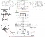
first thing - what kind of speaker protection circuit you are using - it must be made for balanced amp (sense side ground-free)
second - with so much wires flying everywhere, my mind would go motorboating, let alone amp itself
third - post exact schematic you're using, just so we are all on the same page
I was using the diyaudio store speaker protection circuit with the 24v relays. I have now removed it from the chain until I can do more reading about how to re-work it for balanced operation.
Should the DC power wires not be twisted?
Schematic uploaded!
Sorry for the delay I got busy with the holiday!
Attachments
Hello Andreas,
I'm not an expert in these things, but let’s try to improve it. You will need to do some tests to determine what kind of problem it is.
1. Unplug the amp from the mains and remove any input cables and disconnect from the speakers.
2. Disconnect the thermistor (TH1 in post 605 circuit diagram). Measure from the amplifier 0V and input socket signal ground to the chassis to confirm it is open circuit (use high resistance mode, not diode mode). You should be measuring 100's of k Ohms or higher. If you measure a short or very low Ohms, you will have an earth loop problem in your amp and need to resolve it. Reconnect the thermistor (for safety) after you have fixed it.
3. The next test is for common impedance noise. Make sure the input connector signal grounds are NOT joined together inside the amp. Short each input, connect the speakers and re-apply power. If you hear hum, there is a good chance you have a common impedance coupling problem and this means you should look carefully at how the grounds are connected at the PSU side - I assume since this is Nelson Pass design amp board, there are no problems on the amplifier module side. If you hear no noise (or very low noise), then there is a good chance you do not have a common impedance coupling issue, or that it is not your biggest problem at this stage.
4. If there is no noise in step 3, the next test is for a cross-channel ground loop. In a typical cross channel ground loop, the amplifier is quiet with only one input channel connected, or no inputs connected, but when you connect BOTH input channels, then you get hum. To test for this, take a standard 1 metre phono cable and connect it from one input to the other so it forms a loop outside the amplifier. You should hear no noise on a good amp. If you get hum (but none with the cable disconnected both ends), its likely a cross channel ground loop and it is arising inside your amp due to the transformer mag field intersecting a loop formed by the signal ground connection from the one input, through the module, through the 0V power connection to the PSU, out to the other module via the same route and around the external cable. To overcome/reduce this issue, check you using hum breaking resistors (HBR) - see pages 30-41 in the Ground Loop presentation (link below in my signature) and then check point 5 below.
5. Have you routed the input connector to amplifier module cables correctly? The shortest connection is not always the quietest (See pages 61-64 in the Ground Loop presentation). I usually mount these next to each other not separate on either side of the rear panel (although I did this on my earlier amps). You do this to minimize the loop area between the channels. If you join the grounds together where the connectors come into the amplifier, you trap cross channel ground loops inside the amplifier. If your input connectors are on either side of the rear panel and you are running the input cables directly to each amplifier module, you will be creating a very large cross channel ground loop area and you will not help the situation by joining the grounds together on the input sockets in that case. Only bond the input grounds together if the connectors are located right next to each other.
6. This is a class A amplifier with a heavy constant current draw. The transformer will be radiating big magnetic fields compared to a class AB amplifier even with no input signal. If you are still getting hum and all the above is correct, I would lift the transformer out of the chassis a few feet away and run twisted cables to the rectifiers to see if it solves it. If it does, it’s a general mag field problem and you then need to consider a better transformer - hopefully you can avoid that though. For class A amplifier, I always recommend an oversized toroid, with a GOSS band and a pri-sec screen for the reasons I mentioned above.
7. Ground lifter: I usually use a 35A chassis mount rectifier - see page 25 in the 'Ground Loop' presentation. I have not tried the thermistor method, but suspect it works more like an HBR than a true ground lifter. Note on my commercial products I do not use a ground lifter. The amplifier 0V goes straight to the chassis and is bonded to the incoming power safety earth (I do this for safety reasons).
Greetings, Bonsai!
I finally had some time to perform the tests. I believe I have a preliminary conclusion, which in any case will require some guidance.
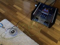
Results/comments in same order as you described:
NB: all tests done with transformer out of chassis. There was no change in hum or noise levels with or without shorted inputs taking the transformer out, and twisting huge gauge interconnects between rectifier and PSU.
1: Done
2: Only unreadably high resistances measured between 0v and chassis, and signal return and chassis with NTC decoupled. Same goes for speaker returns. Conclusion: No ground loop there.
3: shorted inputs, and still the same hum. Only difference with shorted inputs, is less hf background noise. Conclusion (preliminary): I probably have a common impedance issue.
4: I performed this test even though test 3 was positive. Test 4, inputs connected together with one RCA cable, actually increased hum. Also, there was a little bit increased hf noise.
5: this chassis back plate have pre-drilled holes for Neutriks, and the inputs are therefore on opposite sides. So I probably have some cross channel looping, but doubt that is the main problem, since it persists completely regardless of transformer being in or out of chassis.
6: Taking the transformer out and moving it several feet away, provided no change what so ever.
7: Ground lifter against AC loops will not solve my main issue anyways, so I’ll wait.
Conclusions (preliminary):
1: I have a probable common impedance loop. It is possibly exacerbated by a mild cross channel loop.
What in my amp can be causing this? I have some hypotheses, but not sure how good they are:
1: Long interconnects from rectifiers, and using quick connects instead of on board soldering, increases impedance and exacerbates the problem.
2: I have three (3!!) junctions between neg and pos cap bank 0volts at the star point (visible in pic on post 585). In yours and others articles, it is specifically said there should be only one such junction connection.
3: my NTC is connected at this point, but my other ground connections are an inch or two away, on the neg 0v side of the PCB. Plus one of the speaker returns on the other.
4: The lengths of the GND return wires from the gain stage, are of minutely different lengths.
5: Input wires are not shielded.
What do you think is / are my problem(s)? Is it my star or T arrangement messing it up? Is it a combo? Is the tranny still a possible culprit (cap coupling pri/sec), or is that now completely ruled out?
So I plan to do the following, but need to know if the plan is good:
1: Move rectifiers close to the PSU pcbs, and solder connections.
2: Solder trannys to rectifiers
3: Remove all but one junction between cap bank 0v’s. But is one small 16-20 AWG wire thick enough for that connection?
4: Redo general grounding scheme at the star. But it is quite the same as 6L6s in post 1, except for him having 3 junction connections at the rectifier input side of the PCB, and only one at the star side.
5: cut gain stage returns to equal lengths. Also, decrease wire gauge to gain stage from 16awg to half. It does not require much power, and cables are now so thick they are a hassle to twist and work with (solder and so on).
6: Redo/perfect the rest of the wiring, twisting it all properly. Wiring right now is preliminary as I ame testing things to get rid of this hum. But even when wires were twisted and mor properly done, the hum was there nonetheless. But might help other more hf issues though.
7: Move gain stage/FE to back plate, to as far as possible do this the same way 6L6 did. Not expecting change in hum
8: flip heatsinks. Not expecting change in jum
I want to repeat one important thing: The only test that had provided change in hum levels, is moving FE returns to different grounding points.
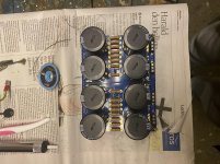
This was a lot of text, and I am sorry for that. I have attached a photo of the testing sequence.
Regards,
Andreas
Attachments
Last edited:
Bonsai:
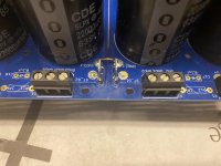
Here are two pictures.
1: Here are the 0 volt connections as they used to be, the quietest I could manage. The black cables are speaker returns. The green/yellow are the front end grounds/returns. In the middle, you see three jumpers/links, creating the junction between neg and pos 0v sides of the PSU. They are not pre-linked.
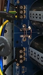
2: This is the PSU as of now. I have removed two of the links, to ensure only one junction. I have added quick connect terminals for ease of testing and flexibility. This now looks like the one in the PSU build guide.
Notice that there are two possible places to link / make junctions between pos/neg 0 volts: one by the output (the one I use right now), and one at the opposite end, the end where secondaries connect. I removed those three links as a test, but there was no change in hum or noise in removing them.
Like I said, I am redoing some of the PSU, and wonder if I should reconnect the links at the opposite, or leave them out. 6L6 uses them, so that is my answer, really. But readig your article, one junction point is max, so I am as usual a bit at a loss.
On the board, you see two points for star gnd, one on each side. I have soldered euroblocks there. What I am wondering, is if using the newly soldered quick connectors will enable me to make a T ground or not. And if so, can I stack all the cables into one connect, or not. This board makes it a bit difficult to follow your golden recipe for which wire to connect the closest to the junction and so on, or so I gather at least.
Regards,
Andreas
Here are two pictures.
1: Here are the 0 volt connections as they used to be, the quietest I could manage. The black cables are speaker returns. The green/yellow are the front end grounds/returns. In the middle, you see three jumpers/links, creating the junction between neg and pos 0v sides of the PSU. They are not pre-linked.
2: This is the PSU as of now. I have removed two of the links, to ensure only one junction. I have added quick connect terminals for ease of testing and flexibility. This now looks like the one in the PSU build guide.
Notice that there are two possible places to link / make junctions between pos/neg 0 volts: one by the output (the one I use right now), and one at the opposite end, the end where secondaries connect. I removed those three links as a test, but there was no change in hum or noise in removing them.
Like I said, I am redoing some of the PSU, and wonder if I should reconnect the links at the opposite, or leave them out. 6L6 uses them, so that is my answer, really. But readig your article, one junction point is max, so I am as usual a bit at a loss.
On the board, you see two points for star gnd, one on each side. I have soldered euroblocks there. What I am wondering, is if using the newly soldered quick connectors will enable me to make a T ground or not. And if so, can I stack all the cables into one connect, or not. This board makes it a bit difficult to follow your golden recipe for which wire to connect the closest to the junction and so on, or so I gather at least.
Regards,
Andreas
Attachments
Last edited:
Looking at your pics, I note differences in wiring and layout compared to 6l6 or my build. while this isnt unusual, when commenting about hum, the difference is sometimes in the details.
Differences I note, first your output boards and outputs are upside down. Again, not critical and may have no bearing but these are merely differences...but things are different than the 6L6 layout. I am not saying that method is better/worse, just noting differences.
You also didnt mount the BA3 board on the back panel. I thought this to be an excellent choice on 6l6's part, doesnt waste space or require the riser, plus it orients the board as if the transformer were mounted vertical (with respect to orientation of boards to transformer), which likely is hum reducing, but I'll be the first to say I dont know it would help with hum, just noting differences.
Again, not a criticism, you could redo your amp this way and it may not help in the least, but this amp as shown is very quiet.
Russellc
Russel, thank you for this post. I agree that I haven’t wired the amp exactly like you and 6L6. But I have now rewired some of it, and the changes are minute wrt to hum. There is however less hf noise, the kind that tires your ears but might be difficult to hear distinctly. The sound is lovely.
I am in a testing process wrt the hum, but also have an exam due for delivery soon, so I have to postpone it a bit.
But there is a couple of major differences between your amp and mine. First, you a have different tranny, like stated before. Second, you have a completely different PSU than me. It looks interesting. Could you point me in the right direction? Wanna check it out.
Bonsai has given me plenty of tips and help, but like I said, I have to wait a bit until I can do all the tests.
What I can say, is that my initial scepticism about the PSU gnd scheme wasn’t all that far out. Apprently, the grounding scheme represents neither a real star or the possibility to make a T. But still, others seem to have succeeded in making it quiet. But that might be one of the issues at play here. We’ll see.
Regards,
Andreas
I'm not sure I've ever seen someone dig into this like you have. A+ for effort.
One thing that I'm not sure you've tried is to move the speaker returns to the PSU GND. I think you still have them running to the amp boards. Yes, it does violate one "rule" (signal and return path being the same), but it follows another (star ground) more closely. It works well for me.
Note Dirk's diagram in post 592 and ZM's guidance in 595 to follow it as prayer. Mine is wired precisely that way with two exceptions. 1) I only using the NTC at the ground lift vs. NTC + bridge. That should have little effect on hum. The rectifier is for additional safety in the event of a certain fault type. 2) I have my PSU bridge and filter section grounds tied at "both ends". That's not shown in Dirk's diagram, but he may have done that.
I am also unsure re: having your audio ground at different potentials for left and right channels. That is interesting.
Dirk, if you happen to see this, do you have your GNDs tied across boards in your PSU in either or both location? I don't see that in the diagram. Just curious.
- Home
- Amplifiers
- Pass Labs
- BA-3 Amplifier illustrated build guide