Thank you for your answer, do you have a precis model?
I made it myself from a switch and bunch of resistors, see here diyaudio | BA-3 Preamp
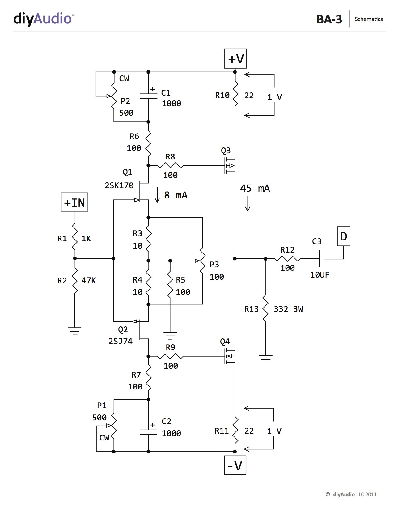
placing here answer to toto34 , given in PM , regarding easier ( and probably proper  ) setting procedure :
usually I don't care about physical orientation of trimpots, simply because there is no standard about that , how they need to be oriented
I always connect voltmeter across adequate points and look at screen of it , to see what I'm achieving with trimpots turning
in this case you need 2 voltmeters - one connected across R10 and another connected across R13
when you get 1V on first and as close you can get to 0V on other , you're done
then you'll have automatically same 1V across R11
you're getting to that iteratively setting P2 and P1
starting point is of course 0 ohm at both trimpots
easiest to check resistance measuring from R6 to rail and from R7 to rail
) setting procedure :usually I don't care about physical orientation of trimpots, simply because there is no standard about that , how they need to be oriented
I always connect voltmeter across adequate points and look at screen of it , to see what I'm achieving with trimpots turning
in this case you need 2 voltmeters - one connected across R10 and another connected across R13
when you get 1V on first and as close you can get to 0V on other , you're done
then you'll have automatically same 1V across R11
you're getting to that iteratively setting P2 and P1
starting point is of course 0 ohm at both trimpots
easiest to check resistance measuring from R6 to rail and from R7 to rail
Good evening again, gentlemen.
What°/w value for heat sinks for transistors FQP3N30 and FQP3P20, or a reference (Mouser, Farnell or others)
I used these initially: Mouser No 532-504102B00, but they were getting quite hot so I switched to a bit bigger ones: Mouser No 532-504222B00.
Last edited:
I used these initially: Mouser No 532-504102B00, but they were getting quite hot so I switched to a bit bigger ones: Mouser No 532-504222B00.
I am also seeking for proper sinking of the input stage power mosfets.
Do you guys with more experience think this is a proper sinking for a stereo build (2 channels , 4 mosfets) of a 32 V shunt powered input stage?
heatsink from ebay
Edit:
I did not mention that after a diyaudiostore failure i had to design my own pcb , and as a consequence i can place them anywhere for a best sinking fit.
Last edited:
soft start wiring in build guide pictures
Can anyone shed light on why the soft start hookup in this build guide is wired differently than suggested in the soft start thread? I'm referring to the implementation visible in the build guide photos.
In the pictures for this guide, I see that the soft start is wired from the AC main switch live terminal to SW2 and from AC main neutral neutral to the soft start board neutral.
The soft start guide recommends wiring AC main live terminal to Live/SW1, then from SW1 to the main power switch and from the other side of the switch to SW2. The neutral goes from AC main neutral to the soft start board neutral.
This appears to me to bypass C1 on the soft start board, which according to the soft start board thread is there to eliminate switch noise.
I've been looking at this build guide as guide to using the soft start since it shows clearly an implementation of its' use. After checking against the recommendations in the soft start guide I noticed the difference. I will be using the soft start in an F6 but found that this particular build guide featured the soft start for inrush rather than the thermistors shown in the F6 build guide.
Thanks, Jim.
PS the build guides are extremely helpful and I find that checking the various build guides for the DIY first watt amplifiers is valuable for seeing several implementations of wiring power supplies and amplifier PCBs.. Thanks 6L6!
Hello,
6 months later i reached finally the output stage biasing step... and I failed:
I need some help setting up the output stage of the single ended burning amplifier.
I power up the gain stage with 30VDC and output stage with 25VDC
(the gain stage is Ba 3 and output stage is Ba 1 specified the schematic a bit lower)
The gain stage is properly biased at 600mv or so and fairly adjusted offset (5-10mA or so).
I used a C3 = 100uF as coupling cap to the output stage so that DC cant contribute.
My issue is that i can not adjust the ofset close to 0 to make the amplifier usable without output capacitor (nothing changes when turning the trimpot P101)
I thought the Mosfets are fried...they're not: (uding the supply set @12V 400mA i connected gate+drain +12V and Source -12V remaining a drop of about 4V)
The offset is rather big... 5-10V measured from output to ground
... i wanted to know if it works even so.... i hooked up a 1000uF output capacitor and it plays music ok.
The ztx450 B->C voltage is about 8,8V
The channel eats up 3-4A from the output stage power supply.
I used this schematic we discussed a while back here post #29
and my ugly implementation is this: ba3-calin.png - Google Drive
Followup:
I left it playing to test at least how fast the heat-sinks heat up completely. It has 9V offset and 0.57V on all source resistors but i connected a capacitor on the output.... i really needed to hear some sounds from that work as a compensation
After 10 minutes i heard some cracks and pops and a harsh sound then no more music... the power draw of the output stage became from 3.5A -> 0A; and the offset 24 V... one side ... down ... the voltage D- to V- became 8.7V
Just finished testing mosfets disconecting source resistor and +12V source -12V drain and gate ...they seem fine..
After it cooled down a bit, done nothing reconnected power and again worked for a short minute with cracks and pops than silent again ... What am i confronting with?
Last edited:
ok
0V57 across source resistors means around 1A2 Iq
positive offset means that lower mosfets aren't opened enough , so you need to increase Ugs (biasing) for that group
confirm that you have ~10V across all zener diodes and , if that's the case - change trimpots for lower half biasing to 5K ...... with 1K you can't reach 4V5 to 5V of needed Ugs
rebias everything carefully and that's it
Attachments
Last edited:
ok
0V57 across source resistors means around 1A2 Iq
positive offset means that lower mosfets aren't opened enough , so you need to increase Ugs (biasing) for that group
confirm that you have ~10V across all zener diodes and , if that's the case - change trimpots for lower half biasing to 5K ...... with 1K you can't reach 4V5 to 5V of needed Ugs
rebias everything carefully and that's it
Checked... The phisically installed trimpots are 5k ... i've checked .... thats a nice spotted typo on the second channel. I have to mention i populated mosfets only on the Q20x side just to be on the safe side and be able to power up safely one chanel at the time.
I will re measure exactly, and add those values on the schematic and come back.
My biggest concern is the intermittent crackling and sudden drop of power consumption... (i tested diodes, bjt and mosfets ....they all work fine out of the circuit )
Last edited:
voltage across zeners?
I was clumsy , writing previous post ..... lower mosfets are biased through/with transistor sensing voltage across source resistor ; which means they're set automatically , while you need to close upper mosfets , if you have positive offset on output
I was clumsy , writing previous post ..... lower mosfets are biased through/with transistor sensing voltage across source resistor ; which means they're set automatically , while you need to close upper mosfets , if you have positive offset on output
P-BAC-S4V20 Output Stage
I apologize if this has been discussed. I have been reading through hundreds of pages of PASS build threads just trying to learn and have yet to see this question pop up. The schematic shows 6 pairs of complimentary output fets. The boards for sale in the store have 3 pairs for stereo (or 6 for mono). Do we need 2 sets of boards for the estimated 40W into 8ohms for a BA-3 in standard config (32V rails)?
I apologize if this has been discussed. I have been reading through hundreds of pages of PASS build threads just trying to learn and have yet to see this question pop up. The schematic shows 6 pairs of complimentary output fets. The boards for sale in the store have 3 pairs for stereo (or 6 for mono). Do we need 2 sets of boards for the estimated 40W into 8ohms for a BA-3 in standard config (32V rails)?
Ultimately, the rail voltage determines output power. More output pairs are necessary only if you have insanely difficult to drive speakers, like parallel Apogees or some funky electrostatics that dip below one ohm or something similarly crazy.
Plus, you need somewhere to mount them and that’s a challenge as well.
To specifically answer your question, yes you would need 2 sets of boards to hold six output pairs. However if you build the amp with one board worth of output devices it will still make full power and still be a fantastic amp. I still have the BA-3 from the guide and absolutely love it.
voltage across zeners?
I was clumsy , writing previous post ..... lower mosfets are biased through/with transistor sensing voltage across source resistor ; which means they're set automatically , while you need to close upper mosfets , if you have positive offset on output
Hello ; excuse the delay,
I added the measurements i took to the schematic : BA3+BA3SE.png - Google Drive
Hello ; excuse the delay,
I added the measurements i took to the schematic : BA3+BA3SE.png - Google Drive
open dedicated thread , post proper pictures and relevant schematics
confirm with measurements that you have established proper rail voltages
I'm frankly totally confused with measurement points and values , you gave in that link
Thanks 6L6! I have very easy to drive 96dB Tekton Design 8ohm speakers. Maybe someday in the future I will convert to the BA-3B monos but for now the 3 output pair stereo should be fine.
For what it's worth, I drive a pair of Tekton Enzo's with a BA3 with 31 volt rails, and it does a great job with 3 pairs.
The Tektons are an easy load in my system, amp can handle more difficult loads fine.
Russellc
For what it's worth, I drive a pair of Tekton Enzo's with a BA3 with 31 volt rails, and it does a great job with 3 pairs.
The Tektons are an easy load in my system, amp can handle more difficult loads fine.
Russellc
This is perfect info! Thanks! I have the Enzo XLs.
I solved the issue ; sorry for the confusion Zen!open dedicated thread , post proper pictures and relevant schematics
confirm with measurements that you have established proper rail voltages
I'm frankly totally confused with measurement points and values , you gave in that link
The issue was an improper idc connector to the bias board that simply did not open the supply mosfets.
I am now at the lasthump ; setting offset ..... i reach the end of P101 ; the offset does not reach 0 it stays at best@ 400 ma so i guess il have to increase R127
Last edited:
- Home
- Amplifiers
- Pass Labs
- BA-3 Amplifier illustrated build guide