Increasing the resistance generally will work.
Some questions:
1) Are the voltages you quoted (+/36.5V with 120VAC, +/-32V with 111VAC) under load?
2) If so, how many of the 0.47 ohm resistors do you have parallel on each rail, and what is the voltage drop across them?
3) Are you trying to get to +/-32V under load with 120VAC?
Some questions:
1) Are the voltages you quoted (+/36.5V with 120VAC, +/-32V with 111VAC) under load?
2) If so, how many of the 0.47 ohm resistors do you have parallel on each rail, and what is the voltage drop across them?
3) Are you trying to get to +/-32V under load with 120VAC?
Hi Dennis,
So, the voltages I gave you were not under load. I didn't apply load for fear of destroying the JFETs. However, upon slowly ramping up under load, I find that at 120.0vac, which is exactly what I have as line voltage at this location in my home, I get +/-32.65vdc on the rails. Is that acceptable? Or are the JFETs doomed? What if I go to someone else's house and connect to a wall socket at 123v, will that be their final farewell?
I'm using QTY 4 of the 0.47ohm 3watt resistors in parallel on each rail
Voltage across resistors (at 120vac primary) is 202mV on B- and 212mV on B-
Also, I noticed that when starting up I see a voltage of about 35vdc on the rail for about a second. I am using the soft start board from diyaudiostore to limit inrush current--not sure if this plays a role in that. Also not sure if I should be worried about it.
My goal is just to have a safe and long-lasting build. I followed the build guide here as closely as possible, hence where I got the target of 32v rails. I'm not opposed to having a lower voltage, as I'm not trying to push any limits. Just want it to sound great and last a while!
As always, thanks for the help.
Thanks for the clarifications.
Page 6 of the BA3 article ( http://www.firstwatt.com/pdf/art_ba_3.pdf ) contains this relevant passage:
"The supply voltage is only critical with respect to the voltage rating of the input JFETs, which
are nominally 25 volts. In actual testing, they break down around 40 volts. I wouldn't worry
about running them as high as 30V. Hot-rodding this circuit would likely involve cascoding the
input Jfets to allow higher voltages."
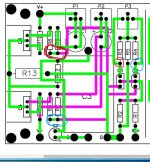
The rating here refers to the drain to source voltage. You can measure that on the two
outer legs of the jfets, though you may have easier access by probing at the connections
coming off the legs to the resistors. (See attached.) Given you are using Toshiba
mosfets I expect you are in the 30-volt range.
Let's say you want to lower that a little by dropping a volt from your rail. You currently
have ~0.47/4 ohm resistance in your CRC power supply and you are drawing about 1.8A.
If you replace each set of four 0.47R resistors, with a set of four 2.7R resistors, you will get
an equivalent resistance ~0.68R and ~1.2V (0.68 x 1.8) voltage drop. I suggest the power
rating of the resistors should be at least 3W.
Here's a sample part:
MOSX3CT631R2R7J KOA Speer | Mouser Canada
Page 6 of the BA3 article ( http://www.firstwatt.com/pdf/art_ba_3.pdf ) contains this relevant passage:
"The supply voltage is only critical with respect to the voltage rating of the input JFETs, which
are nominally 25 volts. In actual testing, they break down around 40 volts. I wouldn't worry
about running them as high as 30V. Hot-rodding this circuit would likely involve cascoding the
input Jfets to allow higher voltages."
The rating here refers to the drain to source voltage. You can measure that on the two
outer legs of the jfets, though you may have easier access by probing at the connections
coming off the legs to the resistors. (See attached.) Given you are using Toshiba
mosfets I expect you are in the 30-volt range.
Let's say you want to lower that a little by dropping a volt from your rail. You currently
have ~0.47/4 ohm resistance in your CRC power supply and you are drawing about 1.8A.
If you replace each set of four 0.47R resistors, with a set of four 2.7R resistors, you will get
an equivalent resistance ~0.68R and ~1.2V (0.68 x 1.8) voltage drop. I suggest the power
rating of the resistors should be at least 3W.
Here's a sample part:
MOSX3CT631R2R7J KOA Speer | Mouser Canada
Attachments
I built my BA3 exactly like the 6l6 did in his build guide. This included the same soft start board, and same 24 + 24 voltage transformer, (same voltage, not same unit) which in my case made for 32 volt rails.
While this has run a few years having no problems, I always thought cascoding the front end might be best option, could allow more rail voltage if one cared to.
The only thing keeping me from it is knowing how the passive parts are calculated. Or, is it not picky, and just poach the circuit used to cascode F5 turbo?
I figure the circuit is made for certain voltage rails and for certain voltage presented to the front end Jfets?
Thanks for any clarity on cascoding front end Jfets in BA3.
Russellc
Rebuild BA-3 FE to function as a pre, sound is awesome, but it adds a faint hiss in the overall circuit. I am not using a regulated psu, but have been able to use it other pre circuits completely silent...I read that a well regulated psu will be able to make it dead quiet, but when Ba-3 is built as a full amp, it would end up using a similar unregulated psu, resulting in a noisier amp...does the FE board require complete isolation from PSU side.
Finally finished building and biasing ba3 complimentary monoblocks (had to put the project down for awhile). I connected them to some cheap speakers to test for the first time, and I'm getting some really weird noise from them that I haven't heard before. Music comes through just fine and doesn't sound distorted, but there is a constant rhythmic thumping/pulsing noise coming out of the woofer of the test speaker.
It sounds like a heart beat but much faster. It is constant and has a repetitive circular rhythm to it. It sounds like two different thumps on both the "on" and "off" beats (musically speaking) for about 7 thumps and then a single thump "on beat" in faster repetition for about 10 thumps, and then back to the two-thump pattern (and it just repeats forever). It sort of sounds like it speeds up and then resets to baseline speed, speeds up again, then resets...etc. Is this called a "moto-boating" noise? I saw that term in some threads while I was trying to browse the forums for advice.
The sound is only audible if the input volume is low, but I'm sure it stays there because as i gently increase the volume i still hear it happening while music is still soft. It's also only audible in the woofer. If i gently place my finger on the woofer i can feel it moving to the thump pattern.
The sound is still audible with no input connected to the amps. I've tested the speakers with another amp and they don't exhibit this thumping noise with another amp.
It happens in both monoblocks and with both PSUs (i've mixed/matched different combos to determine if it's just one PSU or one amp).
I've done some redressing of my wires to try and tidy things up and keep DC wires away from AC wires but the sound still persists.
My logic leads me to think there's some sort of problem with my build since it's happening in both PSUs and both amps in the same way.
I built the PSUs and amps pretty much exactly how they're built in this guide, I even used the same trafo as 6L6. I don't have any snubbers though as I couldn't find values for them in the quasimodo thread, and I don't have a scope (yet) to do a test myself. My guess is this isn't trafo ringing though (but i could be totally wrong)?
Some googling leads me to think it might be a bad cap? I sort of thought that was less likely though since it's happening in both PSUs and both amps (but I could have made the same mistake twice lol).
Any thoughts on what to check out next? I can take some pictures too to help aid in advice collection.
Thanks in advance for your help and advice!
Last edited:
Yup. You're good.
So what should I do? BA-3 or F5T?
I have the BA-3 boards, 5U chassis, two 600va 2x24vdc transformers. And two PSUs eith 4 diode bridges. Cap banks are 60.000 per rail (8x15.000uf 50v per rail), and a total of four rails due to two PSUs.
So a bit of flexibility, and some confinements.
I actuallt really wanna go for the BA-3, and use only obe PSU for less coplexity. But I worry about rail voltage wrt fets, and if i dont go for dual mono, that the cap banks (60k per rail) are in the low range of the recommended 60-80k.
Any experiences or advice? I can rebuild the PSU and change transformer, but kinda want to use what I have =)
Do a BA-3. I have both and love both but the BA-3 is just a touch sweeter. No need for dual mono. This is all my opinion of course. I don’t have my build notes in front of me but i do remember sizing transformers, rail voltage, and PS capacitance to maximize output power while staying just inside recommended parameters.
So it is decided: I will build the BA-3. I’ll post pictures as soon as I get going. Need to get my workshop up and running. Most of the equipment has allready arrived. I am building the complimentary version, and will go single ended.
Anyone know where to find a complete BOM for BA-3 (complimentary), including parts for both FE and output boards? Otherwise I’ll just use the separate BOMs for FE and outputs linked in the store. And the schematic/articles by NP.
Looking forward to this, and for your comments and advice now and in the forthcoming process.
Regards,
Andreas
Last edited:
Having trouble finding both original and alternate MOSFETs for the output stage. Any recommendations for alternate transistors?
I could order from the store, but that will take time as create customs expenses.
I see that Vishay has made an alternative to the 9240, the IRFP9240PBF. They have the same VGS range. First time I have to look for alternate transistors, so I need some help wrt how feasable it is to use alternates, and what values to vonsider IOT not screw it up.
If I do this, I plan to order up a bunch and match dem as recommended by NP.
Thanks,
Andreas
So it is decided: I will build the BA-3. I’ll post pictures as soon as I get going. Need to get my workshop up and running. Most of the equipment has allready arrived. I am building the complimentary version, and will go single ended.
Anyone know where to find a complete BOM for BA-3 (complimentary), including parts for both FE and output boards? Otherwise I’ll just use the separate BOMs for FE and outputs linked in the store. And the schematic/articles by NP.
Looking forward to this, and for your comments and advice now and in the forthcoming process.
Regards,
Andreas
Use the official ones in the store.
Disregard my last. Decided to order up the complete matched set from the store. A rookie like me matching alternative MOSFETs with success? Fat chance...
Matching MOSFETS is pretty easy if you have a precision DMM.
Attachments
Landed voth fets and the BOMs. So happy camper as of now. But could not find neither original or alternative output fets in any store here in Norway, so decided to order up from the store. Used the opportunity to order matched JFETs too. I have some JFETs, i think Toshiba, on a few F5T boards i bought off someone who gave up that project. I’ll post some pics of them here, to help decide whether the real mccoy or not. Thanks!
Landed voth fets and the BOMs. So happy camper as of now. But could not find neither original or alternative output fets in any store here in Norway, so decided to order up from the store. Used the opportunity to order matched JFETs too. I have some JFETs, i think Toshiba, on a few F5T boards i bought off someone who gave up that project. I’ll post some pics of them here, to help decide whether the real mccoy or not. Thanks!
https://no.farnell.com/vishay/irfp240pbf/mosfet-n-200v-20a-to-247ac/dp/1463256?ost=irfp240
https://no.farnell.com/vishay/irfp9240pbf/mosfet-p-200v-12a-to-247ac/dp/8649456?ost=irfp9240
These would come unmatched however. So you would need to order excess and have them matched.
Thanks for all the good advice. So a bit of a sissy ordering matched fets, but to be honest: I am new to this, so kinda good to keep the challenges to a minimum. Right now everything is a challenge, but I am learning thanks to you guys.
Any good tips and hints for good C3 caps / cap combination for the FE? And the other FE caps for that matter. Thought I would get claritycaps for C3, but not very easy to grt hold of it seems. What do you use, and how does it sound? And if you were to do it over again, would you change any of your FE caps?
Any good tips and hints for good C3 caps / cap combination for the FE? And the other FE caps for that matter. Thought I would get claritycaps for C3, but not very easy to grt hold of it seems. What do you use, and how does it sound? And if you were to do it over again, would you change any of your FE caps?
Found all caps I need. Should be fun getting started.
Store MOSFETs are matched to VGS +/- 0,1v. Any experience in here wrt changing source resistors to 0,68 or even 0,47 ohms, like 6L6 suggests if FETs are well matched? How low can I go with the matching quality from the store, and are there any drawbacks/things to consider if going lower than spec? Heat?
Regards on the verge of the weekend,
Andreas
- Home
- Amplifiers
- Pass Labs
- BA-3 Amplifier illustrated build guide