")

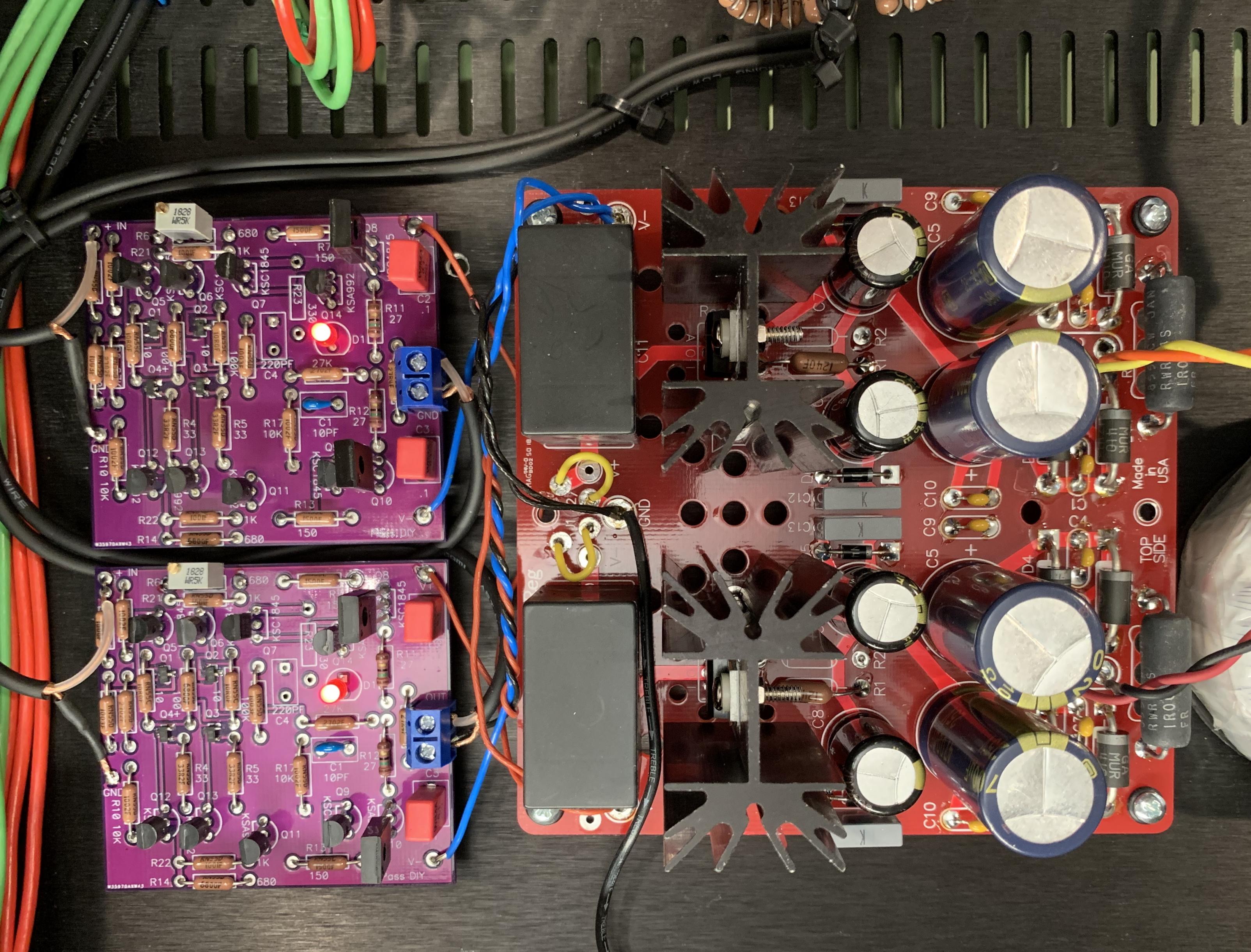
Uhg, do I have a problem. Hooked up across R11, R10 and R12 as instructed. After turning pots, only R11 is showing any activity. Got to .25 volts on R11 and still no activity across R10. R12 has stayed at zero. Am I doing something wrong.. afraid to go any higher. Should R10 increase proportionately to R11 as I turn P1.
R10 and R11 is your bias.
What you are referring to as R12 is your DC offset. But you do not measure ACROSS R12. You measure after R12 and ground. Plus probe of your meter on output leg of R12 or input leg of C3 and negative meter on ground...you can use the ground pad of the PCB.
I'd start with the pots back at zero and start the biasing procedure over again. Because you are not measuring the DC offset you don't know what's going on yet.
Don't be afraid to turn the pots until you get a reading across R10/11. But try to null the dc offset as you go...it's kind of a back and forth game with the pots. The mosfets won't turn on until they reach a specific voltage so sometimes you need to turn a pot a lot until a reading shows up on R10/11.
Worked like a charm. Thanks
R10 and R11 is your bias.
What you are referring to as R12 is your DC offset. But you do not measure ACROSS R12. You measure after R12 and ground. Plus probe of your meter on output leg of R12 or input leg of C3 and negative meter on ground...you can use the ground pad of the PCB.
I'd start with the pots back at zero and start the biasing procedure over again. Because you are not measuring the DC offset you don't know what's going on yet.
Don't be afraid to turn the pots until you get a reading across R10/11. But try to null the dc offset as you go...it's kind of a back and forth game with the pots. The mosfets won't turn on until they reach a specific voltage so sometimes you need to turn a pot a lot until a reading shows up on R10/11.
Okay, I have the boards for BA3-FE and power supply stuffed. Now to figure out how to wire up everything!
Before I solder any wires, I'd appreciate some confirmation that I'm headed in the right direction (or some course correction, if needed) with hooking up the IEC, switch, chassis ground, transformer, and PS board. I'm basically trying to mimic 6L6's build guide, and did my best to decipher how everything connects from his photos... but I'm still unclear on a few things. See attached pic. I tried to draw the wiring as I understand it.
Points of confusion:
1. Should I remove the (what I think is a) jumper plate that connects the fuse box to the IEC? If so, how should the two remaining pins be wired?
2. For wiring the secondaries to the regulator board: does it matter which color wire goes in which of the two AC in holes, so long as the secondaries are paired together (green/blue)?
3. For this dual/bipolar regulator board from Glassware, there's the option to run it in a dual configuration by leaving the two v+/v- sides separate, or in a bipolar configuration by adding jumper wires to connect the two sides. For the BA3-FE, I'm assuming I want to leave it in the dual configuration, right? (I can post a better picture of the board sans wires if that would help. Here's a link to the schematic.
@spryor
3. the ba3 fe needs a bipolar psu - optional two for stereo - so jumper!
1. leave the mains fuse in function for safety reasons!!!
2. you might want to check the phase of the primary/secondary windings
(in series configuration - like in ct - the voltages either null or sum up)
have fun
A.
3. the ba3 fe needs a bipolar psu - optional two for stereo - so jumper!
1. leave the mains fuse in function for safety reasons!!!
2. you might want to check the phase of the primary/secondary windings
(in series configuration - like in ct - the voltages either null or sum up)
have fun
A.
1) Please explain why you are interested in removing that plate.
2) Correct, it doesn't matter as long as you have the secondary wires paired properly.
3) Install J1 and J2 to make the PSU bipolar. The center near the jumpers becomes ground, and V+/V- comes from the outside of the PCB. See photo from different project, but it's wired identically -
2) Correct, it doesn't matter as long as you have the secondary wires paired properly.
3) Install J1 and J2 to make the PSU bipolar. The center near the jumpers becomes ground, and V+/V- comes from the outside of the PCB. See photo from different project, but it's wired identically -
@spryor
3. the ba3 fe needs a bipolar psu - optional two for stereo - so jumper!
1. leave the mains fuse in function for safety reasons!!!
2. you might want to check the phase of the primary/secondary windings
(in series configuration - like in ct - the voltages either null or sum up)
The secondaries look right, each one has two wires coming out next to each other.
Thanks, @Attila and @McQuaide!
So for the mains fuse, I have it "wired" correctly in the photo?
1) Please explain why you are interested in removing that plate.
2) Correct, it doesn't matter as long as you have the secondary wires paired properly.
3) Install J1 and J2 to make the PSU bipolar. The center near the jumpers becomes ground, and V+/V- comes from the outside of the PCB. See photo from different project, but it's wired identically -
@6L6:
1. I didn't see the plate on the IEC you used in your build guide - it looks to my eyes like you had wires coming from each of the pins in both the IEC and the fuse box, which is why I wasn't sure if I should remove the plate. I see now, though, that the plate just functions as a connection between the IEC and the mains fuse, which would align with this diagram which I've been using as a reference to complement your build guide photos.
3. Thanks for this photo - It is very helpful to see this PS board in action in a different build! I'll add the jumpers to make it bipolar.
And thanks to all for your patient replies to these newbie questions. I'm learning a ton and having a great time. More photos and questions to come!
As for the mains, plug a cord in (not to the wall outlet) and check continuity from the prongs to the connections to the transformer and ground.
Checking continuity wasn't on my radar, so thanks for this tip, Mark. It sounds like this is a good general step to take before wiring the secondaries to the power supply board and doing the light bulb limiter test?
Couple things:
On the transformer primary red wires are hot, black wires are neutral, you have it opposite at the switch in your diagram. It will work either way but better to do it correctly the first time.
For the transformer secondaries you need to find the “pair”. The transformer has 4 secondary wires and two of them are pairs on the same winding. You can find the pairs by testing for continuity with a meter. If you have continuity or a low ohm resistance between two wires they are a pair. If it’s a lot of resistance it’s two wires from a separate winding, you don’t want that...it will blow the fuse immediately.
The bulb tester is a good idea but the current draw in this preamp is so low it will only tell you if you have a catastrophic mistake. Like, burn the house down style mistake.
Checking continuity wasn't on my radar, so thanks for this tip, Mark. It sounds like this is a good general step to take before wiring the secondaries to the power supply board and doing the light bulb limiter test?
Following the schematics and tracing connections though end-to-end is always a good step and helps to avoid problems arising from simple mistakes (I know, I make plenty).
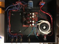
Thanks to your all's help I'm making progress on getting everything wired. I tested continuity last night as suggested by Mark and everything checked out from IEC cord prongs through to the primaries. I still haven't connected the secondaries to the PS board, or the PS to the BA3 board. A poorly-lit photo (sorry - I know that's a faux pas!) is attached of where things currently stand.
A few questions about the next steps:
1. For the 25w bulb limiter test, do you all recommend doing that before connecting the PS to the BA3 board, and then again once everything is connected to begin the biasing process?
2. I've seen reference in the thread to a bleeder resistor, which has me confused. I see the resistor that 6L6 has connected between chassis ground and the PSU. But comments indicate the 100k bleeder resistor is connected to the output cap, which sounds to me like C3 on the BA3 board... I'm confused as to whether these are two different resistors placed in different locations, or one and the same.
3. Related to question #2: I think I saw a comment about someone putting a CL-60 in between the PS and chassis ground instead of the resistor at chassis ground in 6L6's guide. Would that work for this application?
Thanks!
Attachments
1) Initial power up only. Don’t bias it with bulb in place.
2) A bleeder resistor is for discharging the PSU capacitors, not lifting ground of the chassis. The Broskie PSU will bleed itself.
3) Yes, a CL-60 in that position will work beautifully.
Awesome. Thanks, 6L6!
3. Related to question #2: I think I saw a comment about someone putting a CL-60 in between the PS and chassis ground instead of the resistor at chassis ground in 6L6's guide. Would that work for this application?
Thanks!
Hello,
Grounding with a simple resistor 10 Ohm of maybe 1 W or less might be cheaper than a CL60 if i might suggest.
No inrush there to suppress.
- Home
- Amplifiers
- Pass Labs
- The BA-3 as preamp build guide