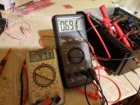
Great idea!gain measured ?
0.7v in to 48v out
Should be about 36db if the calculator is correct.

Maybe its just ment to hiss when beeing a preamp
Attachments
Great idea!
0.7v in to 48v out
Should be about 36db if the calculator is correct.
Maybe its just ment to hiss when beeing a preamp
so , that's the reason for hiss - way too much gain , while you need 12db or so for your needs
you made some systematic mistake (meaning both channels ) - most probably having wrong or mislabeled resistor in some position
recheck everything, report back
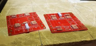
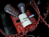
I did infact take a few pictures during construction.
Can't seem to find anything wrong with the written values on the resistors. Guess there could be mislabeling, and then my best bet will be to lift resistors one by one till I find them?
Anyone with a stock but quiet one made gain measurements?
Can't seem to find anything wrong with the written values on the resistors. Guess there could be mislabeling, and then my best bet will be to lift resistors one by one till I find them?
Anyone with a stock but quiet one made gain measurements?
Attachments
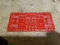
My BA-3 build is coming along nicely. PSU is complete and tested. I'm ready to wire up the board.
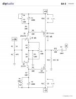
I'm curious how other builders have managed their grounds on the amp board.
Since there are only two dedicated ground pads on each channel--but a need for at least three grounds per channel (signal in, signal out, and PSU) plus a fourth for the recommended 100k resistor from the output cap to ground--are people splicing into the two available pads or just attaching elsewhere on the board's ground path?
I guess there are actually three vacant ground pads with the C3 electrolytic pads vacant, but I haven't seen pictures of folks using that option.
Thanks!
So I lifted one leg of every resistor, measured and checked with the schematics. All the values are spot on as expected after rechecking the print on all the resistors.
Still not found my excessive gain problem
Where are your mosfets?
In one of your pictures the solder joint on r13 did not look very good to me.
Thank you for your reply. But that joint would be after I tried paralelling another resistor over it, giving it a somewhat bloated look on top
Guess the paralelled resistor leg is still in there too. It shouldn't really be the problem as it was hissing before messing up this joint.Both channels give the same amount of excessive gain and therefore a little hiss.
Well, I should have said which picture I was looking at. It was the middle one on post 1131. I use the zoom feature in chrome to make is even bigger. I was thinking that if r13 was open it might clip with the amount of voltage that is showing on your meter at the input. Ok, both channels having the same problem. At the moment I can't think of just one problem that would cause this in both channels.
Thank you. I found the bare board.
- Home
- Amplifiers
- Pass Labs
- The BA-3 as preamp build guide