the link on page 1 for the "galaxy 388" chassis is dead. What is the recommended chassis in the diyAudio store?
thanks
John
I used the Pesante 2U.
How about 400VA, difference is noticeable! Bigger soundstage and deeper bass.
In a linestage? That would be, well, enormous and heavy. I’d be all for additional PSU filtering before the regulator, but massively oversize transformers seem only to make more magnetic hum issues.
I can’t tell a difference between a 300VA and 400VA transformer in a class-A power amp. YMMV.
There is a story behind this. Maybe nostalgic. In the early 80's if I recall right, I had a PSAudio IV full function preamp. It was very good, had a lot of good print at that time.
The story goes that Paul and Stan installed a transformer from an amplifier in a unit they were working or tweaking, though they did not have the stock transformer available.
It was a very big one, suitable for an amplifier. The change for the better in the sound was enough to offer an upgrade for the preamplifier. The PS was an outboard one, so it was easy. I got one. And the difference was impressive. Paul still talks about that adventure in one of his videos. Maybe back then this was a bigger issue because the PS in question was not as sophisticated as the ones used now, you know, regulators, shunts, etc... Allen Wright also mentions this in his book. I had the transformer laying around so I tried it... worked magnificently, no noises, no hum, etc... and as I mentioned I perceived better sound... maybe I'm nostlagic..
massive Xformer plus crude reg is always worse than proper xformer with proper reg
I beg to differ. No rules apply here, some preamp circuits sound better, at least to me, without any active regulation. A few caps, a few (preferably amorphous) chokes is all it takes. And dual mono of course
")
Recently tried that recipe with 500VA per channel and the result was rather nice. Certainly nicer than a 300VA transformer with separate L/R secondaries + salas 1.3. Of course YMMV.
.....Of course YMMV.
follow that
as I'm sayin' - I always prefer a way which is most rattling my cage

To reveal what you like about the different PSU approaches it would be interesting to have an amplifier distortion profile of each approach.
In the context of preamps (class A) i expect the difference in distortion profiles due to a different PS to be zilch. A design with 0psrr may show some vague dependence, but not very likely if there is sufficient local decoupling.
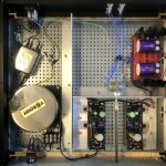
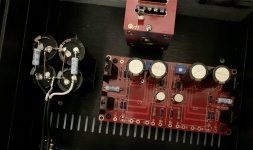
BA3 is warming up at bias ≈890mV. It sounds very controlled and relaxed with fine details. At 90% bias 1V gives 2.5V out. In a few day I will turn up the bias. The FFTs are done with almost no warming up without tinkering with P3s. 1K/1V sine wave from RCA input, so through a 10K pot at minimum resistance. More testing with full bias. Feets and an indicator led is scheduled.
Thank you 6L6 for bildguide, NP for a nice design and everyone else for tributing.
Thank you 6L6 for bildguide, NP for a nice design and everyone else for tributing.
Attachments
BA3 is warming up at bias ≈890mV. It sounds very controlled and relaxed with fine details. At 90% bias 1V gives 2.5V out. In a few day I will turn up the bias. The FFTs are done with almost no warming up without tinkering with P3s. 1K/1V sine wave from RCA input, so through a 10K pot at minimum resistance. More testing with full bias. Feets and an indicator led is scheduled.
Thank you 6L6 for bildguide, NP for a nice design and everyone else for tributing.
Very nice build! I like the isolation of the PS. What type of coupling caps did you use?
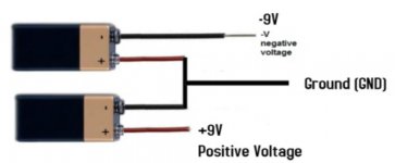
So, I’m using two 24v meanwell SMPS’s (like ACA) to power my BA3 FE. I have no problems getting the positive voltage, but the SMPS I’m using to power my negative rail will not power on. I’ve attached a pic of the wiring config I’m using (sub SMPS for the batteries in illustration)
Any tricks to get this to work properly?
Any tricks to get this to work properly?
Attachments
to get that , SMPS outputs (both pos and neg) must be floating/isolated from case and safety GND
Yep, that did it. Thanks ZM!!!
to get that , SMPS outputs (both pos and neg) must be floating/isolated from case and safety GND
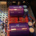
The two SMPS are working fine and feeding the CRC as expected. My question now is grounding scheme - do I take V+/- from the caps and reference the circuit ground to chassis? Or does the circuit ground need to float too?
Attachments
The picture in 1816 is all the progress I’ve made. I simply cut the barrel connectors off, tied the + of SMPS 2 to the - of SMPS 1. I tied that new ground reference to the cap bank ground, along with the new + and - to the corresponding spots on cap bank. Beyond that, I have not attached the +, -, or ground from the cap bank to anything.
The voltages are what I need, just not sure how to proceed
The voltages are what I need, just not sure how to proceed
- Home
- Amplifiers
- Pass Labs
- The BA-3 as preamp build guide