
I am curious about the FFT results. P3 adjustment should change the level of H2 but not H3. What did the FFT look like when H2 was nulled? Did the H3 in both channels stay the same (high in left channel and low in right channel)?
What was the voltage at the preamp output for these FFTs? Typically at reasonable levels of voltage output, I would think that there would be third harmonic present.
What was the voltage at the preamp output for these FFTs? Typically at reasonable levels of voltage output, I would think that there would be third harmonic present.

I can null H2 and increase the level of h3 with P3 in both channels, all of that at -9db output in ARTA. It's just that h3 behaves very differently in the two channels. Not sure what the summed output voltage looks like at that level, but bias across the resistors was around 1.2V. As you suggest, when I go to -6 or -3db (more voltage, but I don't know how much), P3 is always present. I first set them at -3db and was able to set them to similar distortion patterns.I am curious about the FFT results. P3 adjustment should change the level of H2 but not H3. What did the FFT look like when H2 was nulled? Did the H3 in both channels stay the same (high in left channel and low in right channel)?
What was the voltage at the preamp output for these FFTs? Typically at reasonable levels of voltage output, I would think that there would be third harmonic present.
Unrelatedly, yesterday I put in leads and wire clips so I could switch out output caps quickly for A/B testing. They really affect the sound a lot in my system. I tried three different caps that I had around and could immediately hear the differences between each (Mundorf MCap Supreme EVO Oil, Mundorf MCap Supreme MKP, and Jupiter Copper-Foil Paper & Wax). The Jupiters were around from an old tweeter crossover project, but really sound sublime. Obviously they're prohibitively expensive for many, but I think regardless the take home lesson is that it's worth it to try a few different caps and invest in what you can in that location.
Attachments
Further to my previous post, Nelson in his tests of the BA-3 preamp measured distortion with H2 nulled (H3 dominant), with the 1kHz signal output at 2.8Vrms. With a 32V power supply it was 0.0047% THD and with a 24V power supply it was 058% THD. I wonder how your channels compare.
Attachments
Thanks, I'll get in there soon and see what I'm outputting. I'm also curious.Further to my previous post, Nelson in his tests of the BA-3 preamp measured distortion with H2 nulled (H3 dominant), with the 1kHz signal output at 2.8Vrms. With a 32V power supply it was 0.0047% THD and with a 24V power supply it was 058% THD. I wonder how your channels compare
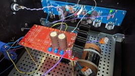
A new problem caused by chasing down a ground loop and the ensuing rewiring work (I did not properly ground my amplifier chassis after building out an external power supply).
One of my boards is passing a signal, but not amplifying. Everything looks fine (i.e., no smoke or charred parts) and I the biasing process works normally, but I only get a very weak signal at output. A working board was outputting 5.53V with a 1k test signal out of ARTA, but I only got .5 something volts with this board.
Any ideas on what I need to test to identify the problem? Given that the circuit is working normally, I'm guessing it's the MOSFETS?
Thanks everyone.
The bias resistors look normal, but I've got absolutely nothing (.5mV) at R3.What are the voltage drops across R3, R4, R10, and R11?
R10=923mV
R11=926mV
R3=0mV
R4=55mV
Thanks.
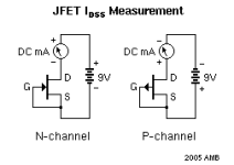
Yep, just -1.6mV across R6.R3=0mV, looks like Q1 2SK170 is bad, as no current is passing through. Another check of that is the voltage drop across R6. 0V drop across R6 would also indicate that Q1 is bad, and not conducting.
So, you'd recommend that I use a matched pair and replace both Q1 and Q2, right?R3=0mV, looks like Q1 2SK170 is bad, as no current is passing through. Another check of that is the voltage drop across R6. 0V drop across R6 would also indicate that Q1 is bad, and not conducting
I've got a pair of old F4 boards I'm not using with matched toshibas in them, so it's not too hard of a task.
Thanks for the help!
I replaced Q1 and Q2 with my other pair from an F4 board. Unfortunately the circuit remains as before. It biased up as normal, but isn't amplifying the signal and I've still got 0mV at R3 and R6.R3=0mV, looks like Q1 2SK170 is bad, as no current is passing through. Another check of that is the voltage drop across R6. 0V drop across R6 would also indicate that Q1 is bad, and not conducting.
I guess I'll try replacing the MOSFETS tomorrow.
It is strange that the mosfets bias up normal but Q1 and attached resistors pass no current. What is the measured voltage at Q3 between its source and gate pins?
If no current passes, that could because of a break, such as a bad solder joint, in the circuit or a faulty component. Check to make sure voltage is getting to the JFET. Check for voltage at R6 relative to Gro
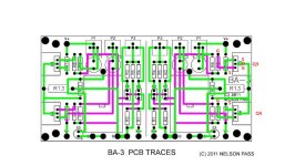
Post some clear pictures of the top and bottom of the board. Perhaps there is something that can be seen.
You can also test the JFET that you removed to see if it good or bad.
If no current passes, that could because of a break, such as a bad solder joint, in the circuit or a faulty component. Check to make sure voltage is getting to the JFET. Check for voltage at R6 relative to Gro
Post some clear pictures of the top and bottom of the board. Perhaps there is something that can be seen.
You can also test the JFET that you removed to see if it good or bad.
Attachments
Thanks for the help Ben.
You were right about the bad component. After replacing the jfets and mosfets, the problem remained the same. In the end I fixed the circuit by replacing R10 & R11. I think I had both a bad solder joint and a bad resistor in one of those locations.
Thanks again for the donated time and help everyone.
- Home
- Amplifiers
- Pass Labs
- The BA-3 as preamp build guide