Well the circuit is doing something ")
Biasing is quite touchy on this board - so like already said probably a bit more patience and less turning on the pots is indicated.
-supply voltages are okay
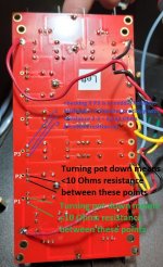
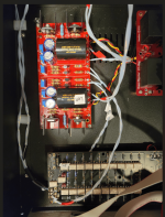
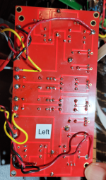
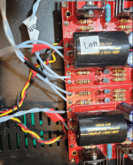
-turn the pots down (see pic attached)
-checking if P3 is in middle position (see pic attached)
-reflowing some solder joints, when in doubt
-with Bias and Offset probes in place turn the thing back up, check if everything reads close to 0
-turn it off
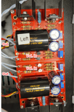
-then place voltage probes across R6+R7
-turn it on
-voltages should read around 0,8 Volts -> if so Jfets are fine -> turn off
-reconnect bias and offset probes and start biasing again with patience - max one half turn P1 then one half turn P2 and so forth.
-when you see something happening reduce your turning amount and wait a bit between turns.
-with biasing you are turning the mosfets on - you want them both to be turned on equally much (if one is turned on more than the other you get a Offest)
-small temperature changes caused by e.g. wind will cause shifts in bias and offset
you will get there with patience - maybe drink a coffee and smoke a cigarette or several along the way
Biasing is quite touchy on this board - so like already said probably a bit more patience and less turning on the pots is indicated.
-supply voltages are okay
-turn the pots down (see pic attached)
-checking if P3 is in middle position (see pic attached)
-reflowing some solder joints, when in doubt
-with Bias and Offset probes in place turn the thing back up, check if everything reads close to 0
-turn it off
-then place voltage probes across R6+R7
-turn it on
-voltages should read around 0,8 Volts -> if so Jfets are fine -> turn off
-reconnect bias and offset probes and start biasing again with patience - max one half turn P1 then one half turn P2 and so forth.
-when you see something happening reduce your turning amount and wait a bit between turns.
-with biasing you are turning the mosfets on - you want them both to be turned on equally much (if one is turned on more than the other you get a Offest)
-small temperature changes caused by e.g. wind will cause shifts in bias and offset
you will get there with patience - maybe drink a coffee and smoke a cigarette or several along the way
Attachments
I believe if you want the resistance of pins 1&2 to match 2&3 on P3, you're going to have to lift one end of the resistors that are tied to the pins to pull the trim pot out of circuit. I would just count the turns and go half way. 25 turn pot would be 12.5 turns. That is relatively accurate.
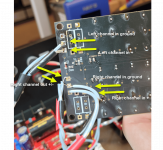
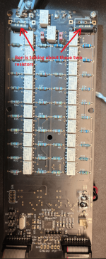
I will check all solder points. And thanks for the encouragement. I agree, there is great support to be found in these forums.At a quick glance, the center solder pad for one of the JFETs looks to be not soldered in. The rest of the circled are hard to tell but look like cold solder joints.
If your MV reading accross R10 and R11 were within around 10mv, you could expect to see a DC offset of 50-100+ millivolts. It gets out of hand pretty quickly. Address those solder joints with a touch of solder and some heat and give it another shot. I didn't look at the Resistors on the top board but maybe someone else will get that.
Also, everyone here had been extremely supportive with me in the past so no matter what my question was. so long as someone is being positive and trying, others being helpful is all I ever expect. This is a great place for all skill levels.
Hi Folks,
Very nice thread. Like many of you I use the Muses volume control board. Mine is coming from Academy audio and is working very nicely with Wayne's BA 2018 linestage.
As per application note from Academy Audio, the error level can be reduced by increasing the preamp input impedance. Here is a screenshot from the Application note and the link to the full document.
View attachment 1033736
https://www.academyaudio.com/_files/ugd/6fd7ca_be4a3abc142e448587231feaa445cf51.pdf
Do you see any potential impact on the sound quality or stability of the BA-3 if I increase the R2 resistor from 47k to 470k?
Thanks.
Any comments?
With my limited knowledge I´d say this should work. Because of the higher resistance there might be a bit more noise, but you can test both ways.Any comments?
Maybe make some noise measurements and post here for further reference.
Edit: with the B1 Buffer Papa has this to say in reference to input impedance "The potentiometers are linear taper at 25 Kohm, but again you can easily use higher or lower values as you like."
B1
I followed your roadmap and crossed the biasing finish line. I've been holding at .995 bias and .0010 offset for five hours.Well the circuit is doing something
Biasing is quite touchy on this board - so like already said probably a bit more patience and less turning on the pots is indicated.
-supply voltages are okay
-turn the pots down (see pic attached)
-checking if P3 is in middle position (see pic attached)
-reflowing some solder joints, when in doubt
-with Bias and Offset probes in place turn the thing back up, check if everything reads close to 0
-turn it off
-then place voltage probes across R6+R7
-turn it on
-voltages should read around 0,8 Volts -> if so Jfets are fine -> turn off
-reconnect bias and offset probes and start biasing again with patience - max one half turn P1 then one half turn P2 and so forth.
-when you see something happening reduce your turning amount and wait a bit between turns.
-with biasing you are turning the mosfets on - you want them both to be turned on equally much (if one is turned on more than the other you get a Offest)
-small temperature changes caused by e.g. wind will cause shifts in bias and offset
you will get there with patience - maybe drink a coffee and smoke a cigarette or several along the way
Thanks for all the assistance that got me to this point.
Next is wiring in the Khozmo remote controlled attenuator.
Those Khozmo attenuators seem to be simple voltage dividers. The input resistor of the BA3 will be parallel to the output resistor of the attenuator to ground. Hence a lower resistor should give you a lower signal if at all and not the other way round. As ZM said a schematic of the Khozmo, a close up of the attenuator as well as the wiring would help.Does that make sense, or should I try 22K?
The BA-3 has a gain of 20db (factor 10) and should be plenty. Maybe you could feed a test tone with 1 or whatever Volts and then measure Voltages (all in reference to ground):
-at input
-after attenuator
-after amp
Attachments
https://www.khozmo.com/link to Khozmo data?
His site doesn't have much info and doesn't even show the resistor board I'm using. Arek has been very helpful all along the way.
Not sure why he thinks I'm using a tube amp. All of mine are diy Pass amps.
Hi Chip
Use lower value for the input resistor
Like 10K
50K is better for tube designs
Best regards
Arek Kallas
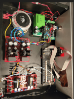
See photos.
Attachments
Chip,
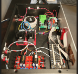
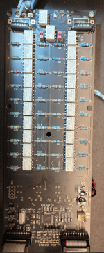
Exactly which Khozmo attenuator do you have? Looking at the board and resistors, I don't think it is a ladder attenuator. It looks like a 20 position shunt, with a 51k input resistor. At full volume you are probably shunting quite a bit of the signal. Arek Kallas is telling you to replace the 51k resistor on the Khozmo board (large black resistor) with a 10k.
Exactly which Khozmo attenuator do you have? Looking at the board and resistors, I don't think it is a ladder attenuator. It looks like a 20 position shunt, with a 51k input resistor. At full volume you are probably shunting quite a bit of the signal. Arek Kallas is telling you to replace the 51k resistor on the Khozmo board (large black resistor) with a 10k.
Attachments
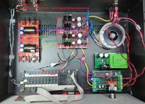
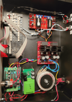
I just remembered. I changed R13 to 600 ohm 3 watt from 330 ohm 3 watt to get more gain per 6L6:show us macro pics how you did wiring of those
you can use signal (anything from 400Hz -1KHz) and measure input and output with your DMM set to Vac
that way you'll know what's exact situation
on max, you must have same input and output
Increase R13. 600ohms would give you close to 2x the gain. (which is only 3db, but if you want a bit more, try it.)
Perhaps per ozorfis above, that has reduced gain with this Khozmo attenuator?
Attachments
Increasing R13 to 600R should not be a problem and give you a bit more gain yes.
I think Ben is right - at max volume you will get approx only half the signal.
Say if you put 1 Volt AC on the Input you only get 0,5 Volt AC at the input of the BA-3 and 5 (stock) - 10 (your mod) Volts AC at the output of the BA-3.
I think Ben is right - at max volume you will get approx only half the signal.
Say if you put 1 Volt AC on the Input you only get 0,5 Volt AC at the input of the BA-3 and 5 (stock) - 10 (your mod) Volts AC at the output of the BA-3.
and give you the benefit of not loading your sources too hard should you ever turn the volume down. So make it 10k - 25k on the Khozmo and 100k - 500k on the BA-3 R2.of course - you can increase 47K input R of BA3 (so R2, ref to schm in post #1) to

Ben, I don't know which model I have. That would be good info.Chip,
Exactly which Khozmo attenuator do you have? Looking at the board and resistors, I don't think it is a ladder attenuator. It looks like a 20 position shunt, with a 51k input resistor. At full volume you are probably shunting quite a bit of the signal. Arek Kallas is telling you to replace the 51k resistor on the Khozmo board (large black resistor) with a 10k.
But I now understand what he [and you] are telling me.
I will swap the 51k resistor out for 10K and give it a go.
- Home
- Amplifiers
- Pass Labs
- The BA-3 as preamp build guide