I think I've found my error.
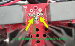
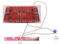
See photos. I failed to install two jumpers which are required for the PSU to function.
So I will get them in and reinstall the board and test again.
Thanks for the help and I will update tomorrow.
Connected the jumpers that I had missed and powered up using a Variac as recommended in the instructions for the PSU.
But at a low voltage, the switch started to smoke so I turned off everything.
I have a PS-22 PSU board ready to go, so I may try that next, as my previous testing had shown the switch and transformer are working correctly.
Short summary: dim bulb tester in place + Switch + Transformer (nothing else) = works, no smell, no light and 20V7 Ac on secondary.
Then you connect only PSU board from Glassware: Dual/Bipolar LV-Reg
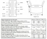
and your switch starts to smell. The switch is rated @4A 250V so your light bulb should be burning very bright by now - is it? With a low wattage bulb like 35 Watts or so you are limited to 100mA.
If above is true, you probably have a short on your PSU, that you have to find. The jumpers in the picture stack the two voltages together V1- and V2+ become your shared ground.
In the picture you can see a solder blob shorting two pads (which is irrelevant in this case as they are ment to go together) but it is stuff like that you should check with your DMM and PCB layout in hand while measuring resistances - with capacitors around resistances might creep up as you measure. Also the red wire is close to shorting out. Maybe your standoffs are too short, something touches the case. If you find no shorts check your diodes and regulators.
Then you connect only PSU board from Glassware: Dual/Bipolar LV-Reg
and your switch starts to smell. The switch is rated @4A 250V so your light bulb should be burning very bright by now - is it? With a low wattage bulb like 35 Watts or so you are limited to 100mA.
If above is true, you probably have a short on your PSU, that you have to find. The jumpers in the picture stack the two voltages together V1- and V2+ become your shared ground.
In the picture you can see a solder blob shorting two pads (which is irrelevant in this case as they are ment to go together) but it is stuff like that you should check with your DMM and PCB layout in hand while measuring resistances - with capacitors around resistances might creep up as you measure. Also the red wire is close to shorting out. Maybe your standoffs are too short, something touches the case. If you find no shorts check your diodes and regulators.
Attachments
Last edited:
Photos of my BA-3 preamp
Hi All,
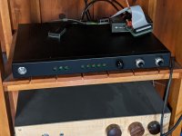
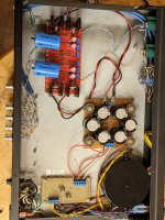
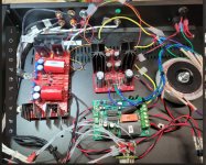
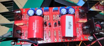
I recently finished a BA-3 preamp, using the boards from the diyaudio store; it's the slim black box in the first photo. The chassis used to be some sort of CCTV control unit I found at Goodwill; nice steel case, and I had hoped to use the BNCs on the back, although in the end I didn't. Transformer is a 50VA Avel Lindberg I found on e**y. The surporise is the PSU, which I expected to just be a temporary solution to get things working, and I planned to put something better in after experimenting a little. Turns out that the CLCLC supply I hacked together with 2200uF caps and some nice inductors I pulled from another Goodwill find (a Bose powered subwoofer unit) is working really well, and hum is only audible at full volume with my ear against the speakers. Right now I'm using it with my diy F3, and liking it a lot.
Next is to do something with the leds on the front; I planned to use them to indicate which input was being used, but I don't really want to look (meaning pay) for a rotary switch with an extra pole. So maybe just use them to show "power on"? Anyone have a better idea? Perhaps I'm being too much of a cheapskate.
Best
Nigel
Hi All,
I recently finished a BA-3 preamp, using the boards from the diyaudio store; it's the slim black box in the first photo. The chassis used to be some sort of CCTV control unit I found at Goodwill; nice steel case, and I had hoped to use the BNCs on the back, although in the end I didn't. Transformer is a 50VA Avel Lindberg I found on e**y. The surporise is the PSU, which I expected to just be a temporary solution to get things working, and I planned to put something better in after experimenting a little. Turns out that the CLCLC supply I hacked together with 2200uF caps and some nice inductors I pulled from another Goodwill find (a Bose powered subwoofer unit) is working really well, and hum is only audible at full volume with my ear against the speakers. Right now I'm using it with my diy F3, and liking it a lot.
Next is to do something with the leds on the front; I planned to use them to indicate which input was being used, but I don't really want to look (meaning pay) for a rotary switch with an extra pole. So maybe just use them to show "power on"? Anyone have a better idea? Perhaps I'm being too much of a cheapskate.
Best
Nigel
Attachments
After an interlude of building and installing Mark's terrific low voltage On-Off switch drives AC mains relay in my four Pass amps, and installing one in my BA-3, I'm reading to finish this project.
I elected to switch out the PSU board for the PS-22 and have successfully gotten 24.1 DCV from both channels out of it.
I wired up the amp board's right channel and tested it for smoke. No smoke. Moved on to biasing.
Which is where I'm stuck.
I've moved P1 all the way to max, while adjusting P2 for off-set and I get R10 .006 DCV, R11 .004 DCV and offset or R12 at .027 DCV.
I've attached my wiring scheme for the right channel.
Attachments
Did you get + and - 24VDC from the PSU?
re: where / how to measure offset. Across R12 is incorrect. See BA-3 amp thread over last few days for great pics and description rather than retype again. I thought you had built a BA-3 amp. I must be mistaken.
You can remove the GND wire between the boards and just run each board to the star. It's optional, and not related, but may be better if you're trying to incorporate a star GND. Also for this circuit, I found it to be much more stable with the inputs shorted while adjusting. YMMV.
Onto the "real" issue. I didn't see any obvious stuffing errors. Some joints look like they could be touched up. Did you start with all pots centered?
What devices are you using for Q3 and Q4? What value did you use for the bias pots? Triple check to make sure P Device is in Q3 and N device is in Q4.
Take readings across R8 and R9. Twiddle P1 and P2. Do they change? Report readings.
Those are some obvious things to try and remove from the pile before going deeper.
Either way, if you maxed P1 in one direction and the build is correct, the bias should have moved. Did you try it in both directions if you started in the center? Did the voltage across R10 or R11 change at all?
That should be a decent start. If anything jumps out, I can try to help. I can help with some things, but hopefully one of the more knowledgable folks will chime in also.
Did you get + and - 24VDC from the PSU?
Yes I got 24DVC for =/-
Nope, haven't built the amp yet. Found the guide for measuring offset, so thanks for that.re: where / how to measure offset. Across R12 is incorrect. See BA-3 amp thread over last few days for great pics and description rather than retype again. I thought you had built a BA-3 amp. I must be mistaken.
Yes I did.You can remove the GND wire between the boards and just run each board to the star. It's optional, and not related, but may be better if you're trying to incorporate a star GND. Also for this circuit, I found it to be much more stable with the inputs shorted while adjusting. YMMV.
Onto the "real" issue. I didn't see any obvious stuffing errors. Some joints look like they could be touched up. Did you start with all pots centered?
I'm using FQP 3P20 & FQP 3N30. Which delivered my key insight - I'm not using 1K pots. I believe that is my key issue. I've ordered them in for delivery tomorrow [early Xmas present to myself].What devices are you using for Q3 and Q4? What value did you use for the bias pots? Triple check to make sure P Device is in Q3 and N device is in Q4.
Thanks very much for your assistance. I will report back after I change out the pots.Take readings across R8 and R9. Twiddle P1 and P2. Do they change? Report readings.
Those are some obvious things to try and remove from the pile before going deeper.
Either way, if you maxed P1 in one direction and the build is correct, the bias should have moved. Did you try it in both directions if you started in the center? Did the voltage across R10 or R11 change at all?
That should be a decent start. If anything jumps out, I can try to help. I can help with some things, but hopefully one of the more knowledgable folks will chime in also.
That's not how it works at all. P1 and P2 are the N and P channel Vfet bias. They have to be increased together to keep things in balance.I've moved P1 all the way to max, while adjusting P2 for off-set
BA-3 front-end is a mini F5. You have to start with them down all the way and turn them up symmetrically until you start getting some changes. Then you can balance increases against offset. It's a lot of two steps forward and one step back. Use three meters, just like an F5.
Chiptech,
You need to adjust P1 and P2 in tandem as Jim wrote.
Which mosfets are you using? Fairchilds or the (low Vgs and unobtainium) Toshiba 2sk2013/2sj313?
What are you values for P1 and P2? Unless you are using the low Vgs Toshibas you likely
need 1K for P1 and P2 to bias up the circuit.
Cheers,
Dennis
You need to adjust P1 and P2 in tandem as Jim wrote.
Which mosfets are you using? Fairchilds or the (low Vgs and unobtainium) Toshiba 2sk2013/2sj313?
What are you values for P1 and P2? Unless you are using the low Vgs Toshibas you likely
need 1K for P1 and P2 to bias up the circuit.
Cheers,
Dennis
I'm using the LS 2SK170/2SJ74 Jfets and have ordered the 1K pots.Chiptech,
You need to adjust P1 and P2 in tandem as Jim wrote.
Which mosfets are you using? Fairchilds or the (low Vgs and unobtainium) Toshiba 2sk2013/2sj313?
What are you values for P1 and P2? Unless you are using the low Vgs Toshibas you likely
need 1K for P1 and P2 to bias up the circuit.
Cheers,
Dennis
thanks. Progress
@Chiptech
Great news. Hopefully the simple change to P1 / P2 will allow you to bias it up properly and null the offset. I haven't read this thread from end-to-end, so I'll point you to helpful things that have been mentioned above from 6L6 and Dennis more specifically from the BA-3 amp thread. I needed a bit of nudging myself on both the F5 amp and the BA-3 front end, so I can share what (I think) I learned, and maybe it will help you to understand why I asked what I asked in a few places.
I had asked about where you started with your pots since that's a common 'error'. It won't necessarily hurt anything, but you need to know which way (CW or CCW) the turns affect the bias of each device (P2 => Q3 and P1 => Q4. If you start 'in the middle' you may have unknowingly turned P1 all the way to the "min" instead of "max". CW turns does not necessarily mean "increase to max". I figured that you just meant that you likely just turned it all the way CW until it clicked vs actually measuring that you'd turned it all the way to its max resistance. Edited to add - CW may still be the correct direction, but even going to max resistance may not have allowed Q4 to turn on... see below re: Vgsth differences and the pot change.
In the mean time, since Q4 had likely not turned on yet P2 could have been sitting there 'around the middle'. At the middle, Q3 was not turned on yet either in this case. Since you thought P2 was the offset pot, you didn't think you had to turn it much to affect the offset.
But wait... why would you want min resistance as the starting point, wouldn't that result in max current vs. min current...? No, it's the inverse in this case. Why gets into a bit more depth, but that drove me nuts.
I had also asked re: the actual devices used for Q3 and Q4 and the pots ( b/c well, that's what 6L6 said in the guide") ). The reason though is that the Vgsth of the original Toshibas is much lower than the Fairchilds. So, in order to get the voltage at the gate of the Fairchilds past the point of turn on and then give them more ooomph past that to up the bias, you need to change P1 / P2 to allow a higher resistance, which in this case results in more available voltage at the gate => more available bias current for the devices. Loosely stated more voltage at the gates to allow the taps to turn open => more current to flow between drain and source.
). The reason though is that the Vgsth of the original Toshibas is much lower than the Fairchilds. So, in order to get the voltage at the gate of the Fairchilds past the point of turn on and then give them more ooomph past that to up the bias, you need to change P1 / P2 to allow a higher resistance, which in this case results in more available voltage at the gate => more available bias current for the devices. Loosely stated more voltage at the gates to allow the taps to turn open => more current to flow between drain and source.
And as 6L6 and Dennis pointed out, one pot is not bias and one pot is not offset. P1 adjusts the bias for Q4, and P2, adjusts the bias for Q3. When you nudge one up, the other needs to be nudged up to around the same, so the offset between them (DC currents relative to output flowing the opposite way) nulls.
I cut and pasted most of that from my old notes, and I hope I got some of it correct. I suppose I could have written all that before, but not knowing what you'd done, it was best just to ask where you started first. I admit to only understanding this at the most basic level. I hope I cut and pasted properly from others' with "real" knowledge. Also, as I've often said, the surest way to get someone the right answer is for me to post the wrong one and have smarter people correct me. 
Here's the relevant excerpt from the BA-3 amp guide re: the bias process. Make sure you measure the resistance once you install P1 and P2 vs. just turning the pots all the way CCW. ZM has beat this into my head finally.
I'd tell you exactly where to measure to be certain, but you can likely figure that out. If not, ask or look up where others have asked (probably me at some point) in the BA-3 amp thread or likely in this thread too.
Enjoy!!!!

Directly pulled from the guide. Note that we've already covered where to measure DC offset, so crossed out.
Bias
Front-end
The procedure for setting bias on the BA-3 FE is almost identical to setting an F5, so this might seem familiar...
The Front-end bias and offset is separate from the output section. Do the FE first. Heck, you don’t even need to connect the output section to bias the FE.
Adjustments (Bias and Offset, set with P1 and P2)
This is easiest with three DMM.
Shorting the input jacks is very helpful, although not strictly necessary.
Before power up, dial pots P1 and P2 to 0 ohms . DON'T adjust P3 during bias
Place one voltmeter (Set to DC volts) across R12 - to observe DC offset
Place a voltmeter (Set to DC volts) across R11 another across R10.
For test - slowly dial up Variac ( presuming that you have one , as man with many skills) up to full mains voltage , observing rail voltage at PSU ....... thinking about max cap voltage ( 25V as in FW ? ) , because with 0 Iq PSU is unloaded and voltage is maxed (It’s useful to have another meter for this…) If nothing is smells bad, and the magic smoke is still in the circuit - leave Variac at full mains ;
IF you don’t have a Variac, you must build a lightbulb mains lead. (with a 25W bulb)
What's important - Iq (measured as the voltage across source resistors; the Mosfet bias) must be very low , offset is irrelevant in this moment .
Now turn one pot one turn ( assuming that you have multiturn pots) then turn other pot one turn. Continue, one turn at a time on each pot until something happens.
Observe voltage across resistors and output DC offset.
Proceed one then second pot , again just one turn
Observe Iq and offset
Again one turn + one turn
Now you are probably in range when you can see which pot is pulling offset in right direction - to 0 . It will feel like one of the pots is controlling the bias on both sides, and the other is controlling the DC offset.
It’s best to increase the bias a bit, and then zero the offset. As you zero the offset you will decrease some of the bias, so it will be two steps forward and one step back. That action is normal.
As you increase the bias and zero the offset, remember to always keep the offset near zero. If you run out of turn on the pots, determine your max bias, with zero offset. (It’s useful for troubleshooting)
Proceed iteratively with pots , while you set - say - 75% of desired bias, with zero offset. Remember, full bias is 1V across R10 and R11, with zero offset BEFORE the capacator. If you measure after the cap there should always be no DC.
Now - put lid on box and let it cook for a while - until you get thermal equilibrium on heatsinks
It's best to use wire/clips to leave those voltmeters in place ;
Open the lid , up bias to - say - 90% of desired one ,while maintaining offset
Put lid on , let it cook.
Check again.
If all is OK - move voltmeters for Bias and offset to other channel and repeat procedure.
Great news. Hopefully the simple change to P1 / P2 will allow you to bias it up properly and null the offset. I haven't read this thread from end-to-end, so I'll point you to helpful things that have been mentioned above from 6L6 and Dennis more specifically from the BA-3 amp thread. I needed a bit of nudging myself on both the F5 amp and the BA-3 front end, so I can share what (I think) I learned, and maybe it will help you to understand why I asked what I asked in a few places.
I had asked about where you started with your pots since that's a common 'error'. It won't necessarily hurt anything, but you need to know which way (CW or CCW) the turns affect the bias of each device (P2 => Q3 and P1 => Q4. If you start 'in the middle' you may have unknowingly turned P1 all the way to the "min" instead of "max". CW turns does not necessarily mean "increase to max". I figured that you just meant that you likely just turned it all the way CW until it clicked vs actually measuring that you'd turned it all the way to its max resistance. Edited to add - CW may still be the correct direction, but even going to max resistance may not have allowed Q4 to turn on... see below re: Vgsth differences and the pot change.
In the mean time, since Q4 had likely not turned on yet P2 could have been sitting there 'around the middle'. At the middle, Q3 was not turned on yet either in this case. Since you thought P2 was the offset pot, you didn't think you had to turn it much to affect the offset.
But wait... why would you want min resistance as the starting point, wouldn't that result in max current vs. min current...? No, it's the inverse in this case. Why gets into a bit more depth, but that drove me nuts.
I had also asked re: the actual devices used for Q3 and Q4 and the pots ( b/c well, that's what 6L6 said in the guide
). The reason though is that the Vgsth of the original Toshibas is much lower than the Fairchilds. So, in order to get the voltage at the gate of the Fairchilds past the point of turn on and then give them more ooomph past that to up the bias, you need to change P1 / P2 to allow a higher resistance, which in this case results in more available voltage at the gate => more available bias current for the devices. Loosely stated more voltage at the gates to allow the taps to turn open => more current to flow between drain and source.And as 6L6 and Dennis pointed out, one pot is not bias and one pot is not offset. P1 adjusts the bias for Q4, and P2, adjusts the bias for Q3. When you nudge one up, the other needs to be nudged up to around the same, so the offset between them (DC currents relative to output flowing the opposite way) nulls.
I cut and pasted most of that from my old notes, and I hope I got some of it correct. I suppose I could have written all that before, but not knowing what you'd done, it was best just to ask where you started first.
I admit to only understanding this at the most basic level. I hope I cut and pasted properly from others' with "real" knowledge. Also, as I've often said, the surest way to get someone the right answer is for me to post the wrong one and have smarter people correct me. Here's the relevant excerpt from the BA-3 amp guide re: the bias process. Make sure you measure the resistance once you install P1 and P2 vs. just turning the pots all the way CCW. ZM has beat this into my head finally.
I'd tell you exactly where to measure to be certain, but you can likely figure that out. If not, ask or look up where others have asked (probably me at some point) in the BA-3 amp thread or likely in this thread too.
Enjoy!!!!
Directly pulled from the guide. Note that we've already covered where to measure DC offset, so crossed out.
Bias
Front-end
The procedure for setting bias on the BA-3 FE is almost identical to setting an F5, so this might seem familiar...
The Front-end bias and offset is separate from the output section. Do the FE first. Heck, you don’t even need to connect the output section to bias the FE.
Adjustments (Bias and Offset, set with P1 and P2)
This is easiest with three DMM.
Shorting the input jacks is very helpful, although not strictly necessary.
Before power up, dial pots P1 and P2 to 0 ohms . DON'T adjust P3 during bias
Place a voltmeter (Set to DC volts) across R11 another across R10.
For test - slowly dial up Variac ( presuming that you have one , as man with many skills) up to full mains voltage , observing rail voltage at PSU ....... thinking about max cap voltage ( 25V as in FW ? ) , because with 0 Iq PSU is unloaded and voltage is maxed (It’s useful to have another meter for this…) If nothing is smells bad, and the magic smoke is still in the circuit - leave Variac at full mains ;
IF you don’t have a Variac, you must build a lightbulb mains lead. (with a 25W bulb)
What's important - Iq (measured as the voltage across source resistors; the Mosfet bias) must be very low , offset is irrelevant in this moment .
Now turn one pot one turn ( assuming that you have multiturn pots) then turn other pot one turn. Continue, one turn at a time on each pot until something happens.
Observe voltage across resistors and output DC offset.
Proceed one then second pot , again just one turn
Observe Iq and offset
Again one turn + one turn
Now you are probably in range when you can see which pot is pulling offset in right direction - to 0 . It will feel like one of the pots is controlling the bias on both sides, and the other is controlling the DC offset.
It’s best to increase the bias a bit, and then zero the offset. As you zero the offset you will decrease some of the bias, so it will be two steps forward and one step back. That action is normal.
As you increase the bias and zero the offset, remember to always keep the offset near zero. If you run out of turn on the pots, determine your max bias, with zero offset. (It’s useful for troubleshooting)
Proceed iteratively with pots , while you set - say - 75% of desired bias, with zero offset. Remember, full bias is 1V across R10 and R11, with zero offset BEFORE the capacator. If you measure after the cap there should always be no DC.
Now - put lid on box and let it cook for a while - until you get thermal equilibrium on heatsinks
It's best to use wire/clips to leave those voltmeters in place ;
Open the lid , up bias to - say - 90% of desired one ,while maintaining offset
Put lid on , let it cook.
Check again.
If all is OK - move voltmeters for Bias and offset to other channel and repeat procedure.
Last edited:
From memory it is good to have P3 set at exact mid-position. So it is set approx. to min distortion.
If P3 afterwards is adjusted (after P1 / P2 procedure) to get more H2 or fine tune to lowest distortion then P1 / P2 needs to be adjusted again (fine tuned).
Then P3 could probably be fine tuned again and then P1 / P2 again.........and then finished.
If P3 afterwards is adjusted (after P1 / P2 procedure) to get more H2 or fine tune to lowest distortion then P1 / P2 needs to be adjusted again (fine tuned).
Then P3 could probably be fine tuned again and then P1 / P2 again.........and then finished.
@Chiptech - MEPER makes a great call-out. I stuck a piece of tape over P3 during my initial set up. Since then, I've seen wise people even use a different color for P3 than P1 and P2. Either way, just do something to help ensure that you don't fiddle with P3 during your setup. When you're ready to intentionally mess with it, you can go down another (albeit super fun) rabbit hole.From memory it is good to have P3 set at exact mid-position. So it is set approx. to min distortion.
If P3 afterwards is adjusted (after P1 / P2 procedure) to get more H2 or fine tune to lowest distortion then P1 / P2 needs to be adjusted again (fine tuned).
Then P3 could probably be fine tuned again and then P1 / P2 again.........and then finished.
@Rodeodave - Looks fantastic!
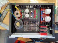
Woah nice. The I-select has enough space? (if built up completely, there's quite some height from HS / cap...Slowly getting towards finishing my compact dual reg BA-3 preamp build.
- Home
- Amplifiers
- Pass Labs
- The BA-3 as preamp build guide