Very nicely done!!
Congratulations! You have a very lucky friend.
Make sure you listen to it a home for a while, you know, for “quality control” reasons.

YA, I think a couple months of QC is required!
How much should the offset move around when you are playing music?Thanks for the compliment!
JT
you can't measure offset while playing ........ eyes and brain are rarely in sync with amp and readout

I wasn't so much measuring it as looking at the way it reacts when music is playing. Okay, I was measuring/monitoring it.
It really does sound great, I haven't hooked it up to my main speakers. Highly modded Tekton DI and PAP Horn1s. I figured if it blew or DCed my drivers, it will be an old pair of Fluance and not the 8k Horns lmao.
It's more a thing, of wanting to know if this is a normal condition.
Last edited:
Yes, offset does move with a signal, so don't worry about it.
Roger that, and thanks.
Noob here. Can anyone give me the lowdown on matching FETs for a F5T v3? I have ordered a matched quad JFET set from the store but I still need the 8 - Bipolar and 16 - MOSFETS. i read in the First Watt article that the bipolars are not critical but have not read much about the necessity of matching the MOSFETS.
Noob here. Can anyone give me the lowdown on matching FETs for a F5T v3? I have ordered a matched quad JFET set from the store but I still need the 8 - Bipolar and 16 - MOSFETS. i read in the First Watt article that the bipolars are not critical but have not read much about the necessity of matching the MOSFETS.
Nelson's MOSFET matching tutorial from the First Watt website:
http://www.firstwatt.com/pdf/art_matching.pdf
Reliable eBay seller for matched MOSFETs here:
IRFP240 / IRFP9240 Complementary Matched Groups | eBay
Noob here. Can anyone give me the lowdown on matching FETs for a F5T v3? I have ordered a matched quad JFET set from the store but I still need the 8 - Bipolar and 16 - MOSFETS. i read in the First Watt article that the bipolars are not critical but have not read much about the necessity of matching the MOSFETS.
You might want to contact our member "h_a" before reaching out to ebay or other as well...
Recently, I decided to increase my BIAS voltage since previously set 360mV gave me about 40 deg C on my heat sinks. New value equal to 420mV is empirically found and allowed me to set my monoblocks to about 55 deg C (21-22 deg C ambient temperature). So, I locked it with 420mV which is 3.6A CC in my case with 4 pairs.
Now, where it is getting interesting…
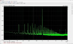
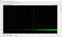
I used FFT to see how they behave and I found huge noise on both units (Left and Right blocks). I suspected my FFT measurement setup for GND loop and tried to find the source of it. Nada… Replaced cables on my FFT setup with nice and professionally assembled Mogami. Same noise. Please see attached images. (I change Fs size and FFT on “No Noise” image to match my RMAA setup. Is it still good representation of FFT). Went into amp and tried to find some GND loop/s there. Also nothing suspicious. I use Rod Elliott’s method of GND elevation and I also removed 10R. Based on many feedbacks, it is still safe with ying-yeng diodes (35A rectifier bridge) since it will allow current to meet Earth in case of catastrophic failure of the circuit. So and technically, it is simulated like no GND connection, but I still got same noise… Same issue when input signal came from preamp that I know for the fact it is very clean. Previous BIAS showed same noise.
So, I decided to try input isolation transformer (Jensen JT-11P-1HPC ) and that is finally defeated my noise issue.
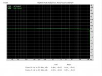
I lost 100kHz FR linearity.., and about -0.5dBv at 20kHz which is no one can hear any way.
Personal appreciation to Salas and L6L for tremendous support during my troubleshooting.
P.S. Please understand that I described my personal case only. Your device is possibly totally fine.
Now, where it is getting interesting…
I used FFT to see how they behave and I found huge noise on both units (Left and Right blocks). I suspected my FFT measurement setup for GND loop and tried to find the source of it. Nada… Replaced cables on my FFT setup with nice and professionally assembled Mogami. Same noise. Please see attached images. (I change Fs size and FFT on “No Noise” image to match my RMAA setup. Is it still good representation of FFT). Went into amp and tried to find some GND loop/s there. Also nothing suspicious. I use Rod Elliott’s method of GND elevation and I also removed 10R. Based on many feedbacks, it is still safe with ying-yeng diodes (35A rectifier bridge) since it will allow current to meet Earth in case of catastrophic failure of the circuit. So and technically, it is simulated like no GND connection, but I still got same noise… Same issue when input signal came from preamp that I know for the fact it is very clean. Previous BIAS showed same noise.
So, I decided to try input isolation transformer (Jensen JT-11P-1HPC ) and that is finally defeated my noise issue.
I lost 100kHz FR linearity..
, and about -0.5dBv at 20kHz which is no one can hear any way.Personal appreciation to Salas and L6L for tremendous support during my troubleshooting.
P.S. Please understand that I described my personal case only. Your device is possibly totally fine.
Attachments
Last edited:
Using separate stabilized power supply for the F5T V2 front end (Voltage Stage)
Dear all hi,
I am in process of building an F5T V2.
Can the front end (Voltage Stage) be powered by a separate stabilized low current shunt type (PSU)?
Will I be able to properly Bias the output due to that (P1 & P2 are located to the front end pcb?
According to the provided schematics for the F5T the store pcb’s have the attached configuration for the front end that includes the bias adjustment for the current gain output stage /pcb’s.
Attachments
I have some questions about bias
Hello,everyone
I’m Wut who is new about making of Am DIY. I am not an electronic technician but I have basically knowledge of electrical.Please recommend and give me the knowledge.
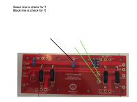
I have some questions about bias , Positions, how many volt for bias, I post the picture below.
Hello,everyone
I’m Wut who is new about making of Am DIY. I am not an electronic technician but I have basically knowledge of electrical.Please recommend and give me the knowledge.
I have some questions about bias , Positions, how many volt for bias, I post the picture below.
Attachments
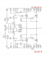
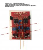
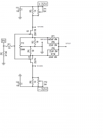
Red lines -- Before power up, dial pots P1 and P2 to 0 ohms ( check with ohmmeter across TP1-2 and TP3-4 on FE board )
Green lines measure bias. From F5T article -
The point at which the diodes conduct is temperature dependent, so you will want to set the bias so that it makes a nice transition above the bias point and doesn't run away when the amplifier gets hot.
If you are competent, fearless and also own a fire extinguisher, you can find this point. Just run the amplifier into a reasonably low impedance until it gets good and hot – as hot as you plan to let it get - ever. Then adjust the bias to a point below where the idle current starts to really take off. You should find that this point is around 0.4 volts across the 1 ohm resistors. If you are a fraidy-cat, then just set it at 0.3 volts, and conservatively fuse the AC line.
I really appreciate your help.
Red lines -- Before power up, dial pots P1 and P2 to 0 ohms ( check with ohmmeter across TP1-2 and TP3-4 on FE board )
Green lines measure bias. From F5T article -
The point at which the diodes conduct is temperature dependent, so you will want to set the bias so that it makes a nice transition above the bias point and doesn't run away when the amplifier gets hot.
If you are competent, fearless and also own a fire extinguisher, you can find this point. Just run the amplifier into a reasonably low impedance until it gets good and hot – as hot as you plan to let it get - ever. Then adjust the bias to a point below where the idle current starts to really take off. You should find that this point is around 0.4 volts across the 1 ohm resistors. If you are a fraidy-cat, then just set it at 0.3 volts, and conservatively fuse the AC line.
Hi all.
I hope tomorrow or in two days to be able to make the first start up of the amplifier at least for one of two channel and I'm a little afraid of making a mistake so, to be sure, I would like to ask you some questions always thanking you for the time you dedicate to me.
I would like to be more precise in the question already asked by wuttichai referring to post #594 and the answer by 6L6 at #595 of this thread.
First, start and short-circuit the input. Then with an ohmmeter I have to test 0 ohm between TP1 and TP2 of the FE PCB and the same with the same ohmmeter between TP3 and TP4, right?
Subsequently I understand that I can disconnect the multimeter and connect a voltmeter between TP2 and TP3 of the PCB of channel P, another voltmeter between TP2 and TP3 of the PCB of channel N and the third voltmeter (as shown with orange lines in https: / /www.diyaudio.com/forums/atta...0-04-34-am-jpg) between G and O / P of the FE PCB. Am I wrong?
Since I would like to be calm, if I understand correctly I set only 0.3 V between TP2 and TP3 on the PCB of channel P and the same on TP2 and TP3 on the PCB of channel N noting that there is 0 V between G and O / P of the FE PCB, right?
Thank you very much
Last edited:
Hi wondering how one might make this a monoblock that is fully balanced?
Thanks
Double all the power supply stuff and put'm in different boxes.
Thank you for another great build guide 6L6!
Finished a mono-block build last night of F5T V2 using two 4U chassis I had from previous builds. Everything fired up and biased without incident. They are running a bit cooler than expected. With the bias set at .400mV and measuring right where one of the Mosfets attaches to the heat sink I am seeing 40C. Will let them run for a day and then start raising the bias to see when I reach 45C.
View attachment 860845
Finished a mono-block build last night of F5T V2 using two 4U chassis I had from previous builds. Everything fired up and biased without incident.
They are running a bit cooler than expected. With the bias set at .400mV and measuring right where one of the Mosfets attaches to the heat sink I am seeing 40C. Will let them run for a day and then start raising the bias to see when I reach 45C.View attachment 860845
- Home
- Amplifiers
- Pass Labs
- F5Turbo Illustrated Build Guide