Like i mentioned earlier, i wasn't the original builder. That said, i notice something that might be at issue. On my front end boards, R25 and 26 are 1K (which matches value in F5T article , V2 schematic).
Reading this build thread, It is mentioned these should be 10K (which would match the schematic of the V3 shown at beginning of thread) . Based on location I'd guess this may be at the root of my problem. Any thoughts?
Reading this build thread, It is mentioned these should be 10K (which would match the schematic of the V3 shown at beginning of thread) . Based on location I'd guess this may be at the root of my problem. Any thoughts?
You mentioned R25 and R26. But the v2 schematics on page 9 here:
https://firstwatt.com/pdf/art_f5_turbo.pdf
do not show these resistors. They are in the V3 version (p,13) and are part of the cascode circuit.
If you are using the cascode (ie, you have Q7 and Q8 populated) then R25=R26=10k and R27=R28=4.75k are fine. The whole point is to roughly limit the voltage through the jfets Q1 and Q2 to about 1/3 of the rail voltage. (Note the R26 value in the v3 schematics has a typo)
Please measure the voltages across R3, R4, R5 and R6.
The voltages across R5 and R6 need to be 4-ish volts for biasing. If you can't
bias, it's possible because these voltages are too low. That can happen from
a combination of high Vgs output mosfets/ low Idss jfets. If this is what's happening,
increasing R5 and R6 should solve the problem. (You'll have to turn P1 and P2 back
down before powering up again so you don't accidentally start with too much current.)
Don't change your R5 and R6.
Your R3/R4 voltage values suggest problems with your jfets.
Only the 69mV reading is good. The others basically mean your jfets are 'off', which
explains why you can't bias.
Can you please check your parts against the schematics to make sure you have
the correct parts installed.
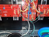
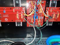
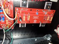
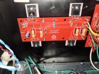
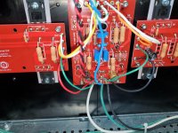
Also, it may help others to spot potential problems if you can post photos of your pcb.
Your R3/R4 voltage values suggest problems with your jfets.
Only the 69mV reading is good. The others basically mean your jfets are 'off', which
explains why you can't bias.
Can you please check your parts against the schematics to make sure you have
the correct parts installed.
Also, it may help others to spot potential problems if you can post photos of your pcb.
Please feel free for details, angles, part values if they aren't clear
Attachments
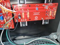
I'm not familiar with the F5t pcb and I don't see anything obvious.
I suggest you check the soldering, in particular from R5 down to R6
(F5t v2 schematics on p9: https://firstwatt.com/pdf/art_f5_turbo.pdf )
Touch up any soldering as needed. Then make sure your rail voltages
are correct and try measuring the R3 and R4 voltages again.
Also please check the part values and placement, including the jfets.
If the R3 and R4 voltages are not good, you likely will need to pull the jfets out
and test them and there's a chance you will need replacements.
Last edited:
Turbo V2 utilizes 32V rails. I'm using a AN-6224 transformer. AN-6224 - 600VA 24V Transformer - AnTek Products Corp
- Home
- Amplifiers
- Pass Labs
- F5Turbo Illustrated Build Guide