AN 6225
4A slo blo 250v
You may be blowing fuses regardless of the functionality of your amp circuit.
A good rule of thumb is to use the VA of the transformer divided by the mains voltage as a starting point. Assuming you are in the USA, 600 / 120 => 5.
You may get away with 4A slow-blow, but personally, I would get some 5A fuses. Others may also have an idea or two.
re: post 1120
Good questions. I need a bit of clarity. You begin by asking about the ground lift circuit, but all your questions seem to relate to inrush current limiting. When in doubt, post the schematic(s) and circle the area in question.
A great resource for the answers is in the PSU build guide. Everything below is in the context of the inrush current limiting.
As you pick up knowledge here and there, and maybe before you find and read the answers, consider below and see if you can arrive at the answers. Below is an approach I might take.
1) "How" does the thermistor or pair of thermistors do what it does? How does it function in the circuit to limit the inrush of current?
2) What is temperature coefficient? What happens if it's positive or negative as it relates to temperature rise and the associated resistance of the part?
3) From the spec sheets of the CL-30 and CL-60 (see Mouser etc to get the spec sheets) what would expected cold resistance be (at room temp) of each part?
4) What would the expected resistance be under the operating conditions of your amplifier? What would the part's (or parts') expected temperature be under normal operating conditions?
One vs. two parts
1) Two CL-60 vs. the CL-30. What are the key differences from the spec sheet between the two parts?
2) With USA mains, with a dual primary transformer, and with the primaries wired in parallel, do you "need" to have a thermistor on each of dual primaries? Note how the single thermistor connects to the hot and neutral legs of the the dual primaries vs. how the two CL-60s are connected. How would one thermistor behave vs. two? See as a comparison the primaries wired in series for 240VAC and where the thermistor sits in the circuit. Picture a positive 1/2 cycle and a negative 1/2 cycle and how you think the current flows through the primary windings.
Any advantages or disadvantages? Why would one perhaps choose a CL-30 if they were only using a single part vs. using 2 CL-60s? Note that one of the PSUs is for a standard First Watt design, while the other is for the F5T. What major difference between an F5 and an F5T might have led the circuit designer to make the choices they made in their respective PSUs?
Again, excellent questions - I think you can figure it out. If not, post again.
Edited for clarity - Mainly edited around describing CL-30 vs. two CL-60 questions and an error around my original F5T, CL-30 wiring description.
Last edited:
IAIMH,
Awesome teaching style buddy. That's exactly how I go about learning this. Ask WHY questions with a particular interest on the FUNCTION of each part.
To be honest though I didn't start this quest until after I had successfully built a few kits. Building then became mundane.
Understanding the engineering is now a lifelong pursuit.
Best,
Anand.
Hi Anand -
That's very kind. Thank you. It seems our journeys were/are similar. I became fascinated with "how it all works" after I successfully built a few kits. I still remember your encouragement throughout my M2x build. I'm still a novice, but it's become what will be a lifelong pursuit to try and grasp a bit of the magic.
Hope to see you at BAF again this year.
Cheers,
Patrick
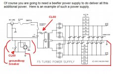
I clearly was mixing portions of the same drawing in my question. The inrush limiter on the ps is taking the surge of the initial charging of the filter caps ( which appear as a dead short at turn on ( before they charge). From a novices understanding it'd seem a higher resistance ( impedance?) Would be desired and if you could split the 2 primaries in half ( which you can) it seems prudent to do so , assuming that when the CL heats up its resistance drops to near zero.
Part 2 , the ground lift circuit is a tremendous mystery to me. I can wire as its drawn. I can't wrap my head around what magic is occurring with the high current bridge. Also I can't see there ever being enough current to make that current limiter ever warm enough to drop in resistance.
Part 2 , the ground lift circuit is a tremendous mystery to me. I can wire as its drawn. I can't wrap my head around what magic is occurring with the high current bridge. Also I can't see there ever being enough current to make that current limiter ever warm enough to drop in resistance.
You can do a bit of reading to go more in depth, but I totally understand if you don't want to take that on at the moment. I'd recommend going with the F5T PSU schematic and following it if you're unsure.
re: the function of the bridge as part of the ground lift - see also long discussions re: safety factors of using a single CL-60 (or similar) as the ground lift. Unless you're really into it, I'd skip that for now. You can find all that in the PSU build guide thread and others also.
re: the function of the bridge as part of the ground lift - see also long discussions re: safety factors of using a single CL-60 (or similar) as the ground lift. Unless you're really into it, I'd skip that for now. You can find all that in the PSU build guide thread and others also.

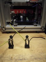
This is a pic of my groundloopbreakers - made of a 35A-bridge-rectifier and
a CL-60 thermistor. You have the recipe in the article of Nelson Pass about the
F5T:
https://www.firstwatt.com/pdf/art_f5_turbo.pdf
Cheers
Dirk
a CL-60 thermistor. You have the recipe in the article of Nelson Pass about the
F5T:
https://www.firstwatt.com/pdf/art_f5_turbo.pdf
Cheers
Dirk
Attachments
- Home
- Amplifiers
- Pass Labs
- F5Turbo Illustrated Build Guide