I have the older V2 of the boards.
You can use 14awg solid core on the +ve -ve and G of the power input.
And you can use 14awg solid core on FE board.
Stranded 14awg, no way. but you can use 15.5awg stranded
Thanks for that clear cut answer. I feel this info will be useful for all future F5 builders.
Once again for the benefit of future builders, TeaBag's boards allow the use of 12 AWG solid/14AWG stranded in the same holes.
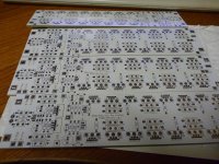
You mean these ones?
Yes they have bigger holes. I've never actually measured them though.
BTW if anyone is interested, PM me.
Yes and the PSU board. +/_/G on both PSU and amp board are 2.0mm
I plan on emulating this build with the same rail voltages. i.e +/-32V but in a non-cascode build. The Antek 6224 transformer used by 6L6 is no longer available. The closest they have is the Antek 10425 which is a 1000VA with 25V output (AN-10425 - 1000VA 25V Transformer - AnTek Products Corp). Is that suitable to use?
Or would it be preferable to use the Hammond 1182T24 (625VA, 48V @ 13.02A in series/24 @ 26.04A in parallel), or 1182U24 (750VA, 48V @ 15.63A in series/24V @ 31.26A in parallel)?
(Hammond Mfg. - Toroid Power Transformers - (1182 Series))
Or is there another option?
thanks
Or would it be preferable to use the Hammond 1182T24 (625VA, 48V @ 13.02A in series/24 @ 26.04A in parallel), or 1182U24 (750VA, 48V @ 15.63A in series/24V @ 31.26A in parallel)?
(Hammond Mfg. - Toroid Power Transformers - (1182 Series))
Or is there another option?
thanks
sorry I have a question: I have a house in dual mono power supply consists of 2 transformers 2x28v 500 goes each and two banks of capacitors from each 6x22000uf, I could use them to build a F5 turbo v2 or 2x28v voltage is too high?
output are about 2x35vdc.
which is the maximum voltage for the 'F5tv2?
and yet, it is true that using the IRFP240 and irfp9240 the sound is sweeter
thanks to all
output are about 2x35vdc.
which is the maximum voltage for the 'F5tv2?
and yet, it is true that using the IRFP240 and irfp9240 the sound is sweeter
thanks to all
The output from 28v across a bridge rectifier is 39.6v. Are you figuring for CRC power supply and getting 35v?
I don't think it will make that much difference at 35v, but you could use a larger resistor value to drop the voltage.
Just watch the dissipation on the CRC resistor.
I don't think it will make that much difference at 35v, but you could use a larger resistor value to drop the voltage.
Just watch the dissipation on the CRC resistor.
Last edited:
thanks for the reply, now I have 2 resistanze crc to220 equal to 0.1 ohm 20w for each bank, thus putting an appropriate resistance calculated using Ohm's law could achieve the desired V right?
Try this site:
Resistors
I have a mental block that doesn't allow me to understand or remember Ohms law.
")
CRC resistor is not the way to go for shaving of voltage. you only end up with a hugh loss of dynamics and 0.5V less rail voltage.
bias current must be less then the limit for the diodes to start conducting. and not more then the heatsinks and transistors can handle. i would not og over 1A pr device for the transistors sake. but not over 400mV across 0.5ohm source resistors (to be on the safe side) do to diode conduting.
bias current must be less then the limit for the diodes to start conducting. and not more then the heatsinks and transistors can handle. i would not og over 1A pr device for the transistors sake. but not over 400mV across 0.5ohm source resistors (to be on the safe side) do to diode conduting.
test points on the N and P channel boards
Hi all,
First thanks 6L6 for the excellent guide! The photography is outstanding and of great help to us newbies!
I have used your guide to set P1 and P2 for a scant 200 Ohms for start up. 4% of maximum seems safe, am I foolish?
(This 200 Ohm figure I got by measureing R between TP1 and TP2 for P2, P1 is measured TP3 to TP4. The correlation of the numbering seems strange/wrong but it does not work the other way around...)
What are the test points on the N and P boards for? Have they a use?
I'd also like confirmation on what exactly is meant by "source resistors". I'm always questioning my take on what "the big boys" mean when they give direction.
Many thanks!
Hi all,
First thanks 6L6 for the excellent guide! The photography is outstanding and of great help to us newbies!
I have used your guide to set P1 and P2 for a scant 200 Ohms for start up. 4% of maximum seems safe, am I foolish?
(This 200 Ohm figure I got by measureing R between TP1 and TP2 for P2, P1 is measured TP3 to TP4. The correlation of the numbering seems strange/wrong but it does not work the other way around...)
What are the test points on the N and P boards for?
Have they a use?I'd also like confirmation on what exactly is meant by "source resistors". I'm always questioning my take on what "the big boys" mean when they give direction.
Many thanks!
- Home
- Amplifiers
- Pass Labs
- F5Turbo Illustrated Build Guide