final connections questions
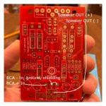
1. I should use a COAX cable from RCA input to "In" and G on the bottom of the FE board (opposite side of P-Ch and N-Ch Gate connections)
2. Out to speakers should be from O/P on top of FE board (same side of P-Ch and N-Ch Gate connections) speaker +, and speaker - from G four pad spot on bottom of FE board, next to +Ve and -Ve connections.
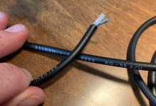
3. 18 AWG wire for speaker wires will be sufficient? I'm not sure I could get anything larger into those holes.
I'm planning on wiring up BOTH XLR and RCA connectors. Anyone know of a schematic I can follow to get the wiring correct? This was somewhat helpful
How To Wire XLR to RCA Connectors | BoomSpeaker.com
1. I should use a COAX cable from RCA input to "In" and G on the bottom of the FE board (opposite side of P-Ch and N-Ch Gate connections)
2. Out to speakers should be from O/P on top of FE board (same side of P-Ch and N-Ch Gate connections) speaker +, and speaker - from G four pad spot on bottom of FE board, next to +Ve and -Ve connections.
3. 18 AWG wire for speaker wires will be sufficient? I'm not sure I could get anything larger into those holes.
I'm planning on wiring up BOTH XLR and RCA connectors. Anyone know of a schematic I can follow to get the wiring correct? This was somewhat helpful
How To Wire XLR to RCA Connectors | BoomSpeaker.com
Attachments
Hi Guys, a very busy day at work and I’m just trying to acknowledge and thank all of those who chimed in to help to this point. Sangram, thank you so much for the excellent explanation, it totally makes sense. Jim & Dirk, thank you guys as well. Dirk, I still have have a little while to go before I give up on this bad-boy although sometimes I question why. I will take that advice as well. This is the situation last night, I don’t like it but don’t know enough about it yet.
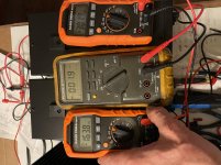
I powered up last night plugged into the dim bulb which is plugged into the variac with 2 amp fast blow fuses for the double transformers. I wasn’t taking any chances this time around. I lowered pots p1 & p2 back down all the way to start from 0. No smoke, nothing heating up. After a while I felt it it was safe and removed the dim bulb but used the variac so I could dial up the power slow so the surge wouldn’t smoke the 2 amp fuses. As I started bring the bias up I noticed there is a huge bias difference between the p & n boards. I brought the bias up to 300mv on the p channel board and 160mv on the n board with 0 offense to. They both change up and down with no issues but what would cause such a difference? Does this mean the MOSFETS are not matched properly? Any thoughts or suggestions?
I powered up last night plugged into the dim bulb which is plugged into the variac with 2 amp fast blow fuses for the double transformers. I wasn’t taking any chances this time around. I lowered pots p1 & p2 back down all the way to start from 0. No smoke, nothing heating up. After a while I felt it it was safe and removed the dim bulb but used the variac so I could dial up the power slow so the surge wouldn’t smoke the 2 amp fuses. As I started bring the bias up I noticed there is a huge bias difference between the p & n boards. I brought the bias up to 300mv on the p channel board and 160mv on the n board with 0 offense to. They both change up and down with no issues but what would cause such a difference? Does this mean the MOSFETS are not matched properly? Any thoughts or suggestions?
Most often the cause is poorly matched MOSFETs, or if you bought a matched set from the store, one might have picked the wrong set to pair the n channel or vice versa. The ones I bought for my BA-3 were matched in a bag for each channel containing both N and P channels. The stores fets should not be the problem, though it can not be ruled out. Is it possible you chose the wrong n or p pair for one of the channels?
But there can be other reasons too, though I am not qualified to help you there...
Are you sure all the source resistors are the same values?
Don’t give up, man! You’ll nail this. And what you learn will profit you in every future project!
Regards,
Andy
But there can be other reasons too, though I am not qualified to help you there...
Are you sure all the source resistors are the same values?
Don’t give up, man! You’ll nail this. And what you learn will profit you in every future project!
Regards,
Andy
Last edited:
Hi Andy, thanks for the input and encouragement. I purchased the F5T kit from the store, all $90 worth. I got a bag of p & n mosfets along with the cascode transistors in the same bag. Nothing was labeled so I assumed they were matched as they advertise. I am 100% positive they’re in the right spot. I did not change any of the source resistors and I did check all of them prior to be sure didn’t smoke when the mosfets blew up.
Last edited:
Hi Guys, a very busy day at work and I’m just trying to acknowledge and thank all of those who chimed in to help to this point. Sangram, thank you so much for the excellent explanation, it totally makes sense. Jim & Dirk, thank you guys as well. Dirk, I still have have a little while to go before I give up on this bad-boy although sometimes I question why. I will take that advice as well. This is the situation last night, I don’t like it but don’t know enough about it yet.
I powered up last night plugged into the dim bulb which is plugged into the variac with 2 amp fast blow fuses for the double transformers. I wasn’t taking any chances this time around. I lowered pots p1 & p2 back down all the way to start from 0. No smoke, nothing heating up. After a while I felt it it was safe and removed the dim bulb but used the variac so I could dial up the power slow so the surge wouldn’t smoke the 2 amp fuses. As I started bring the bias up I noticed there is a huge bias difference between the p & n boards. I brought the bias up to 300mv on the p channel board and 160mv on the n board with 0 offense to. They both change up and down with no issues but what would cause such a difference? Does this mean the MOSFETS are not matched properly? Any thoughts or suggestions?
measure voltage drop on both of the P-ch fets. 300mV on the P-ch and 160mV on N-ch and still have 0mV offset. That sounds like you have 1 active P-ch mos and 2 active N-ch mos.
I suggest measuring voltages across all the source resistors. DC offset shouldn't
lie and if you can trim the dc offset then the current on each half can't be too far off.
Did this channel previously suffered the flameout? If so, you may have damaged
source resistors as well.
lie and if you can trim the dc offset then the current on each half can't be too far off.
Did this channel previously suffered the flameout? If so, you may have damaged
source resistors as well.
measure voltage drop on both of the P-ch fets. 300mV on the P-ch and 160mV on N-ch and still have 0mV offset. That sounds like you have 1 active P-ch mos and 2 active N-ch mos.
AudioSan & Dennis, there’s no doubt you’re on to something. Measuring across each source resistor, these are the readings I have:
P Channel-
R17=300 R18=299 R19=0v R20=0v.
N channel-
R21=163mv R22=163mv R23=137mv R24=139mv
Dennis Hui, yes, same channel that smoked. You mentioned source resistors, although they were checked while in the circuit, should I unsolder on side and check?
The Vgs on the P mosfets is high enough to give 0.6A through Q3 then I would
expect Q4 to be 'on'. I think AudioSan has outlined the possibilities.
What resistance values do you measure across R17 and R19?
Edit: Just saw the latest posts. Glad you found the problem.
expect Q4 to be 'on'. I think AudioSan has outlined the possibilities.
What resistance values do you measure across R17 and R19?
Edit: Just saw the latest posts. Glad you found the problem.
Last edited:
ALL of you guys are great and thank you! I got it up and running and the bias is within a few mv’s of each other with the voltage nulled. I’m going to go very slow this time around, although I went slow last time and it still smoked lol. I’m going to keep a low fuse for now until I build more confidence in it.
Last edited:
- Home
- Amplifiers
- Pass Labs
- F5Turbo Illustrated Build Guide