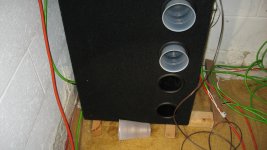
The attached photo shows the the Jensen Bandpass Subwoofer [JBS]. It sits in the left corner of the room. The clear/see-through side of JBS faces the wall to the left of the pic. The ports face the listener of music. The electrical connections to the woofer are to the right of the pic. The two white objects are 16 oz plastic cups; which are maleable. They plug the ports of chamber A per the previous post. They make an effective tight seal. Note the following:
- The top port [for example] is plugged first.
- A pinhole is put in the bottom face [or side] of the second cup before it is inserted in the next port down.
- The purpose of the pinhole is to vent the air pressure which develops when a second untreated cup is inserted in the port to seal chamber A. I suspect that without the pinhole, and with a tight seal of chamber A, that the cone of woofer A will be pushed forward into chamber C, and the cone of woofer B will be pushed backwards into its chamber B. This creates an undesirable and persistent offset of the cones.
- After sometime, the cones of the two woofers re-establish their neutral status. The pinhole can be taped over with electrical tape.
Attachments
Expanding the use of Acoustic Absorber based on Jensen Bandpass Subwoofer
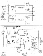
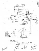
The attached picture AcAb7 is mostly that shown in post #40 [refresher diagram] ; but with two important additions which appear at its bottom right corner where Vo is.
The attached picture AcAb7 is mostly that shown in post #40 [refresher diagram] ; but with two important additions which appear at its bottom right corner where Vo is.
- I added an enclosed subwoofer at Vo. Note the phase of its leads.
- I enabled an RCA-style output to feed another independent power amp.
- The Jensen Bandbass Subwoofer [JBS] sits at the floor corner as I described in Posts 40 and 41.
- On top of it sits a 3-way commercial A/D/S L730 loudspeaker [from the 1980's]. It is in great working order, and rarely used. My current interest is to use its 12" woofer [4 Ohm] for acoustic absorption.
- On top of L730 sits an enclosed subwoofer; the driver of which almost reaches the ceiling corner as I had described in a previous post. This subwoofer is a dual voice coil with both of its coils connected in parallel.
- Unchanged CSPA as described earlier. Its output drives the woofer at the ceiling corner [Wc]. Its output is also a signal level input to a utility power amp.
- This utility low power amp is a SONY mini hi-fi component stereo system which was rescued from being trashed. It has tone controls which are set at their neutral positions. It also has a volume control which is a valuable asset in this application of acoustic absorption.
- The SONY amp so happens to invert the phase of its input signal. It drives the L730 loudspeaker [Wd]. Note the phase of the loudspeaker in relation to [Wa + Wb] of JBS and Wc.
Attachments
Update
The series connected voice coils in the above designs do not adhere to the teaching of the patent. They fight each other as the common output current flows through both of them. But not all is lost. Their prototypes generated electrical signals which measured air/sound pressure of the low end. These signals were amplified, inverted etc. and played back via an additional loudspeaker to disrupt standing waves. Perceptible differences in soundstage, clarity of music were heard.
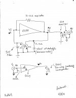
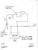
The attached diagram adheres to the patent teaching. In it, the voice coils of a dual voice coil [DVC] subwoofer are electrically isolated. The prototype has a tendency to buzz, whistle etc which is a show stopper; but this problem is surmountable. Please note the following:
The series connected voice coils in the above designs do not adhere to the teaching of the patent. They fight each other as the common output current flows through both of them. But not all is lost. Their prototypes generated electrical signals which measured air/sound pressure of the low end. These signals were amplified, inverted etc. and played back via an additional loudspeaker to disrupt standing waves. Perceptible differences in soundstage, clarity of music were heard.
The attached diagram adheres to the patent teaching. In it, the voice coils of a dual voice coil [DVC] subwoofer are electrically isolated. The prototype has a tendency to buzz, whistle etc which is a show stopper; but this problem is surmountable. Please note the following:
- The principal components are a DVC subwoofer [no internal crossover for simplicity], CSPA and an iron power transformer [120V to 25.2V at 50VA] or a 5:1 step down ratio..
- Tried 10:1 [not enough feedback], and 2:1 [too much feedback] which caused oscillation.
- The power transformer gives electrical isolation between the voice coils, and the option to connect VC2 for proper phase.
- The indicated phase of the shaded sine signals, and that of the voice coils [triangles] are and must be identical to give positive acoustic feedback. This is the invention.
- Both voice coils now work together in harmony.
- As air pushes against the cone [inward], VC2 reacts by further pulling in the cone to diminish air pressure.
- The feedback resistor [270 Ohm and the Zobel [4 Ohm in series with 55 uF NP electrolytic] cured audio oscillations.
- A signal generator [50 Hz] was used to differentiate positive from negative acoustic feedback.
- Pushed a signal through and measured signal levels. Reversed the the phase of VC2 [negative acoustic feedback], and re-measured signal levels. They were lower in magnitude than with positive acoustic feedback.
- This observation agrees with the fact that a general negative feedback decreases amplifier gain while a controlled positive feedback increases gain.
- I got output signals Vo [isolated] and Vo' for further processing to study the need or not so as to further disrupt standing wave.
- The signal with positive acoustic feedback can be amplified [SONY utility amp with volume control] and directed to another independent loudspeaker. This loudspeaker may be put in the same floor corner or the ceiling corner.
- Now I need to listen to music.
Attachments
Objective Test of Acoustic Absorber
This is an objective test method which showed the Acoustic Absorber [AcAb] works as taught in/by the Pass patent. Let's look at the attached picture which is loaded with info. Most important is to mind the relative phase of signals where indicated.
This is an objective test method which showed the Acoustic Absorber [AcAb] works as taught in/by the Pass patent. Let's look at the attached picture which is loaded with info. Most important is to mind the relative phase of signals where indicated.
- The top part was the diagram shown in the previous post with two changes. First, I added a momentary pushbutton switch to short the output of CSPA [Vo] to ground so as to disable AcAb. No damage was done by this action. Second, a line level signal was taken from the secondary of the output transformer to feed the SONY voltage source amp. This amp inverts the phase of its input signal.
- The middle part of the picture, shows the SONY driving an A/D/S L300C bookshelf loudspeaker [4 Ohms, 5.25" Woof, two-way].
- The bottom part of the picture shows the placement of the loudspeakers relative to the left corner of the room. The Jensen Bandpass Sub [JBS] is idle and sits smack in the corner. Next to it is the Dual Voice Coil [DVC] subwoofer which lacks an internal x-over. Its voice coils are labelled VC1 and VC2 in the diagram. In front of JBS sits L300C on the floor. Note the locations of the sound pressure measurements with a Realistic analog sound level meter [SLM].
- SLM was put in front of DVC subwoofer close to the edge of its enclosure. Scale was 70 dB, C weighting, and slow response.
- The room was excited with a continuous low frequency sine wave sound via an auxilliary loudspeaker-amp combination which was not related to those under discussion.
- The low frequency was swept in the range of 40-60 Hz so as to find the one which gave the highest reading/value of sound pressure.
- In this room [20' by 20' by 9'], the prominent frequency was ~48 Hz.
- Adjusted sound pressure to 70 dB [midscale of meter]
- Turned on power to CSPA so as to only energize VC1 and VC2 but not the SONY.
- This action decreased sound pressure by 1 dB.
- Shorted Vo of CSPA to ground with momentary push button switch. This action raised sound pressure back to 70 dB.
- This is the point of the invention: sound pressure decreases due to AcAb. This meant that the parent sound pressure of the standing wave [SW] was diminished as expected.
- Relocated SLM in front of L300C. Initial sound pressure was ~69 dB
- Turned on the SONY and maxed its volume control. Sound pressure decreased by a hefty 5 dB.
- Shorted Vo to ground [disabled both CSPA and SONY signals], sound pressure in front of L300C jumped back up to 69 dB.
- I played this game over and over.
- Clearly, via the volume control on the SONY it can easily deliver intermediate values of sound pressure reduction or disruption of SWs. But; where is the limit which is worthy of continued study?
- The momentary pushbutton switch is on a long leash which reached the music listening location. Readily perceptible differences were heard due to the switch's on and off choices. I preferred the AcAb [CSPA and maxed SONY] engaged, The music was big, live. spacious and tonally balanced.
Attachments
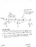
Please find attached the diagram of another and simpler circuit than shown in the previous post. Oscillation in the form of buzz, whistles was a challenge I faced with circuits of this invention; because they must utilize intentional positive feedback. I am pleased to say that I have gotten good at managing and surmounting this problem. Consider the top portion of the diagram:
- The amplifier CSPA utilizes negative feedback via the resistor 16-20 Ohm. Increasing the value of this resistor to 25 Ohm causes buzz.
- The Zobel at the output [0- 8 Ohm] in series with 47uF NP electrolytic affects oscillation. Buzz erupts when the value of this capacitor is decreased. The resistor in this Zobel is not needed at all for stability,and can be deleted.
- The small AC power transformer [5 VA, 120 VAc to 36 VAC] isolates and steps down the output signal Vo for presentation as an input signal Vs to the independent Sony voltage source power amp.
- Why is further amplification needed by the SONY amp which drives and independent loudspeaker L300C that is located in the same left corner as the DVC subwoofer?
- CSPA and its associated components give a modest 1 dB decrease in sound pressure. I have come to believe that this is an inherent signature attendant to the DVC approach as compared with that utilizing a ceramic microphone /loudspeaker as taught by the Pass patent.
- Sony/L300C enable the loss in SPL due to standing waves [in front of L300C] by an additional 5 dB minimum.
- There is an upper limit at about ~7-10 dB reduction of SPL in front of L300C before system breaks into oscillation.
- Objectionable hiss became pronounced at this higher reduction in SPL. This suggested that the tweeter of L300C needs to be disabled, or use instead an enclosed woofer; with a suitable low pass filter.
- L300C can face the listener, the floor [6 inches on stilts per patent requirement] or the ceiling.
Attachments
Is CSPA special or unique for this application?
But; of course it is a special amp. I brewed it myself with a lot of inspiration from you all contributors of other threads in the Pass Labs Forum. I am glad to say that it is not unique at all for this patent app. So, I am setting aside my zeal for it, but will show in future posts that run-of-the mill power amplifiers will do as good or maybe a better job than CSPA.
The Pass Labs Forum is dedicated to building small and big simple Class A amps. I hope that CSPA has found a good home as a DIY build. My latest revision of it is attached. The chips idle at ~100 mA each via the capacitor-bypassed 12 Ohm power resistors. I eliminated degeneration resitors [in series with 12 Ohm resistors] to maximize gain.
May inject amplifier apps for CSPA in the Thread by Zen Mod which is entitled "Ultrasimple SIT PP amp from BAF, or SIT Beast with a Thousand PSUs". CSPA may be seen to behave as a fake PP SIT amp.
Attachments
Acoustic Absorber based on Voltage Source Power Amp
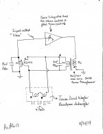
The attached picture is a diagram of an Acoustic Absorber [AcAb] which used a voltage source power amp [SONY]; instead of the current source power amp of past posts [named CSPA].
The principal components are:
The attached picture is a diagram of an Acoustic Absorber [AcAb] which used a voltage source power amp [SONY]; instead of the current source power amp of past posts [named CSPA].
The principal components are:
- An integrated power amp like the SONY which I wrote about in past posts. Its Tone Controls [Treble and Bass] were set flat. Its Volume Control was maxed.
- A 50 VA step-down iron core power transformer [120 V to 25 V]. I liked it for its "isolation" ability, and for allowing control over the level of the positive feedback signal.
- The primary coil of the power transformer was connected to the power output port of the SONY. Its secondary coil drove 2 independent boxed subwoofers
- The first is a dual voice coil [DVC] enclosed subwoofer which sat smack in the left corner. Voice coil 1 [VC1] is the "microphone" which fed the input port of the SONY called "Video". VC2 was energized by the secondary coil of the power transformer. This DVC subwoofer is the main acoustic sensor of Standing Waves [SW] which was subjected to overall positive loop feedback [via VC2] per the teaching of the Pass patent.
- The second independent subwoofer was the Jensen Dual 10 inch Woofer Bandpass Subwoofer [JBS] which I wrote about in past posts. It sat with its 4 ports next to DVC subwoofer.
- Both independent loudspeakers worked together to effect a net decrease of 2-4 dB SPL [50 Hz] at each port of JBS, and at the edge of the DVC subwoofer facing its driver. I thought that was an impressive result.
- The film capacitors were needed to suppress high frequency oscillation unrelated to buzz and whistles.
- AcAb was stable against audio oscillations. But, oscillation as buzz was easily triggereg by boosting the Bass. Another whiny oscillation was triggered by decreasing Treble.
- I have another DVC subwoofer, and a Visonic Dual 10-inch Woofer Bandpass like JBS which sit in the Right corner.
- Since SONY has 2 power amps, I will have a stereo AcAb which will establish acoustic symmetry for stereo music. I'll keep you posted.
- I will assemble another AcAb which will utilize an Electret transducer as described in the Pass patent for comparison with the above approach of a DVC subwoofer.
Attachments
The attendant patent by Pass uses an Electret microphone which gave him a simple; but effective design.This electret microphone also simplified the Acoustic Absorber as shown in the following diagram. Please note its principal components:
- A KEMO potted module amp. It is rated to deliver 12 W into 4 Ohms. Its schematic is unknown. Still available commercially
- The Jensen Bandpass Subwoofer [JBS] which I showed in past posts.
- An electret microphone I bought many moons ago at Radio Shack. Its ultra miniature acoustic element goes to an in-line tube which houses a button battery [1.5 V], buffer [FET] and an On-Off switch to save the battery when idle.
- The overall length of the shielded cable from the acoustic element to the terminating 1/8 inch plug is 16 feet.
- The frequency response of electret is 70 Hz to 16KHz. Output impedance is 1 K Ohm. It mated nicely with the input of the KEMO amp.
- A regulated power supply of 15 V.
Attachments
Pictures
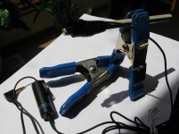
A picture of the electret microphone is shown. The acoustic element [black] was taped to the tip of the shell of a spent pen. This assembly was clamped and a stand was rigged. The vertical and horizontal orientation of the acoustic element was continuously adjustable to suit. Also shown is the in-line black tube which houses an on-off switch, a battery, and most probably a FET that is connected in the common source config, its load resistor of 1 KOhm, and an output coupling cap [see Wikipedia]. Its electrical signal ends at the shown plug.
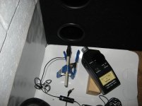
A second picture shows the electret microphone stand facing the bottom port of the Jensen Bandpass Subwoofer which sits in the left corner. Also shown is an analog SPL meter which was set on the 70 dB scale, C-weighting, and slow [average] needle response.
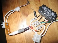
A third picture is the amp. Quite simple. The input resistor [820 Ohm] is across one of the connecting white blocks.
I was pleased with this performance.
A picture of the electret microphone is shown. The acoustic element [black] was taped to the tip of the shell of a spent pen. This assembly was clamped and a stand was rigged. The vertical and horizontal orientation of the acoustic element was continuously adjustable to suit. Also shown is the in-line black tube which houses an on-off switch, a battery, and most probably a FET that is connected in the common source config, its load resistor of 1 KOhm, and an output coupling cap [see Wikipedia]. Its electrical signal ends at the shown plug.
A second picture shows the electret microphone stand facing the bottom port of the Jensen Bandpass Subwoofer which sits in the left corner. Also shown is an analog SPL meter which was set on the 70 dB scale, C-weighting, and slow [average] needle response.
A third picture is the amp. Quite simple. The input resistor [820 Ohm] is across one of the connecting white blocks.
I was pleased with this performance.
- Mic was initially turned off at the switch of its in-line black tube.
- The room was excited with a 50 Hz. signal which gave 0 dB on the 70 dB scale.
- Amp was powered up, and then the mic switch was turned on.
- Sound pressure decreased 3-4 dB at each of the 4 vertical ports of the Jensen subwoofer. More dips in SPL were measured when the meter was inserted inside each port.
- If sound pressure happened to increase by 3-4 dB instead of decrease as above, then reverse the leads to the loudspeaker.
- Two variables affect the stability of this system against audio oscillation. The value of the input resistor to the KEMO amp [820 Ohm], and the horizontal distance of the electret element from the outside of the port.
- The patent suggested a distance not to exceed 3.5 inches between the mic and loudspeaker.
- So keep the value of the input resistor constant and creep the microphone stand slowly towards the port until the system breaks up into oscillation. Then back away the stand a smidgen from the port to quiet the howling. At this setting the system will perform its best.
- Or put the microphone stand at an arbitrary distance from the port [e.g. 3 inches]. If system oscillates, lower the resistor value to that which will quiet the howling. If system does not oscillate, then slowly increase its value to the point of howling. Back off a smidgen to get the ideal value of the input resistor to the KEMO amp.
Attachments
A current source amp [CSA] unlike a voltage source amp [VSA] lacks some ability to exert control over the loudspeaker which it is driving. In an enclosed cubic music room, random air pressure that is reflected from the room boundaries returns back to it, and thus constantly pushes against and pulls at the woofer cone of this loudspeaker. The performance of this loudspeaker has been altered; compared to it operating outdoors. CSA unlike VSA does not correct for this acquired distortion. But this woofer has an opportunity to [meaning may] behave as a simultaneous and inadvertent acoustic absorber as described in the Pass patent. For example, the woofer is pulled back [towards its magnet] by the CSA's signal, and returning high air pressure simultaneously pushes against the cone so as to help it move further towards the magnet. This is reduction of reflected air pressure at the cone. By contrast, a resultant inverse high air pressure at the cone can equally or not happen [opposite of Pass Patent]. Ponder the thought of this loudspeaker driven by a CSA sitting at a corner
I stimulate the music room with a 50 Hz signal to generate standing waves at the corners, I used a diy power CSA to drive a pair of 15 inch musical instruments which are bolted to the ceiling. They focus their output [like a stereo pair] towards a sweet spot/point where my ears go on the floor. When the left 15" loudspeaker is stimulated, the SPL meter read 70dB at the left and right corners. When both 15" loudspeakers were energized in phase, the SPL meter showed a loss of ~4 dB at the left corner. It is good to have this inadvertent acoustic absorption; but perplexing as to its cause! But, I will use a VSA to stimulate the same 15" exciters to root out the cause of this phenomenon.
I stimulate the music room with a 50 Hz signal to generate standing waves at the corners, I used a diy power CSA to drive a pair of 15 inch musical instruments which are bolted to the ceiling. They focus their output [like a stereo pair] towards a sweet spot/point where my ears go on the floor. When the left 15" loudspeaker is stimulated, the SPL meter read 70dB at the left and right corners. When both 15" loudspeakers were energized in phase, the SPL meter showed a loss of ~4 dB at the left corner. It is good to have this inadvertent acoustic absorption; but perplexing as to its cause! But, I will use a VSA to stimulate the same 15" exciters to root out the cause of this phenomenon.
Moving towards a stereo acoustic absorber.
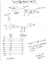
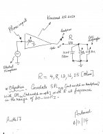
The following acoustic absorber was assembled, and its objective performance measured in the frequency range of 40 Hz to 100 Hz.
1. Amp was a Threshold S/150; left channel. Its performance is well established, was overkill [powerwise] for this app; but is an industry standard [IMHO].
2. A 10 inch dual voice coil [DVC] subwoofer. Both coils [8 Ohms each]were connected in parallel. This loudspeaker was described earlier and sits in the left corner.
3. An electret microphone on clamps was also described earlier. It was put ~1 inch away from the center of the woofer's dust cap.
4. The room was stimulated with sound in the range 40-100 Hz
5. A SPL analog meter was put ~6 inches from the DVC driver at its 70 and 80 dB scales.
The simple schematic is attached in the top part of the picture. The acoustic absorber was stable; meaning it was not inclined to oscillate like buzz or whistle.
The table below the diagram was the objective performance of the acoustic absorber which I thought was impressive. A reduction of 4-6 dB in sound pressure due to standing waves was observed in the range of 50 -80 Hz.
I also have an KENWOOD KR-6050 receiver from the early 80's [60 W/Ch into 8 Ohms; overkill too]. I'll use it instead of S/150 with the DVC sub and electret microphone for comparison
Best regards
Attachments
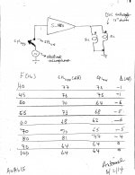

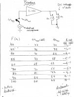
More results
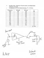
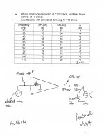
I followed-up on the above suggestion by Mr. Pass. But first, I repeated the baseline experiment which initially gave impressive results. The results were reproducible; give or take 1-2 dB. The first image showed the circuit of this baseline experiment. The data column to the far right [delta dB] shows the old [impressive] results; and the repeated results side by side which are still very good IMHO. The second image showed my attempt to do the suggested experiment by Mr. Pass.
1. The signal from the electret microphone was amplified using the AUX port of the Kenwood receiver. Its volume control is highly valuable. Its Treble control knob was turned fully counterclockwise to cut the highs.
2. The power output of Kenwood was stepped down [and isolated] with an iron core power transformer [120V:25.6V; 50VA]. This generated the input signal to S/150 [Vo]. The role of the film capacitor [10 uF] across resistor [33 Ohm] was to further cut the highs.
Here was the power-up protocol:
1. Turn on power to Kenwood
2. Turn its volume control to minimum [~7 o'clock]
3. Turn Treble control counterclockwise to minimum.
4. The Bass tone control stays at its flat center point
5. Turn on the switch attendant to the electret microphone.
6. Turn on power to S/150
7. Slowly increase the volume control of the Kenwood.
8. At about the 10 o'clock setting of its volume control, the system began to oscillate.
9. Fortunately the oscillation was in the mid-range and not in the low bass which could destroy the sub driver..
10. Back off a step on the volume control to quiet the oscillation.
11. Collect data. Best to use a digital instead of the analog SPL device I have.
The data show a possible improvement of 1 dB in favor of the new system. If this improvement is taken to be measurement error, the old and the new data say that the baseline system was almost there, and did not need to be fussed with.
Attachments
A general DIY
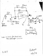
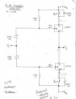
I suggested in Post #51 to replace Threshold S/150 with Kenwood KR-6050 receiver. This DIY is hoped to be general in its application since second-hand receivers like Kenwood may be purchased cheap online, and besides a Threshold power amp is a rarity nowadays. After some tweaking, the attached diagram/schematic is a functional and stable Acoustic Absorber [AcAb]. Please note the following:
1. The Electret Microphone is connected to the input of the PHONO amp of receiver This input has the standard of its era input impedance of 47 Kilo Ohm attendant to using a magnetic cartridge. The amp also has an industry standard gain and equalization.
2. The output of the power amp is switchable to Headphone output or Loudspeaker A or B
3. Headphone position allowed the measurement of SPL [off] of standing waves before they are attenuated or disrupted. This means the Pass invention is not enabled.
4. Loudspeaker position A allowed the measurement of SPL[on] of the attenuated/disrupted standing waves [the Pass invention].
5. The purpose of the power resistor in series with the loudspeaker is to lower the damping of the power amp; meaning to move this voltage source amp in the direction of a current source amp. The resistor and the film capacitor are a low pass filter which also cleans up the trace of the scope from noise.
6. The setting of the volume control is ~ 9 o'clock for maximum system gain and was on the verge of a mid range oscillation.
7. A preliminary performance trial with R = 16 Ohms showed encouraging results in the frequency range of 30 - 80 Hz.
Results are forthcoming.
Attachments
Very interesting Antoniel. congratulations.
I have measured peaks of 20 db in a room at 60 hz. Of course these are room dependant.
Just a few thoughts that might help.
Keep the output of the anuuling speakers in the bass range, I would be very worried if it was doing something to the midrange.
It is great you can control de volume as to adjust how much anuuling it would be making.
Are you able to control also the frequency range in which the anuuling starts and ends, from 30 to 80 hz. This is why you lower all the treble output on the Kenwood amp?
I think this is a wonderful idea, to be able to put a couple of "Anuuling Subwoofers" in your room which will get rid of all the standing waves without touching the signal on your main system. I would set it for the range in which I already know my room has resonances on, and then adjust volume by ear.
Right now I am using an Behringer DCX to tune down a few dbs form my woofers.
Inching closer to a simple DIY
The performance of the general DIY Acoustic Absorber [Post #55] was determined by using either the AUX or PHONO inputs [of the Kenwood receiver KR-6050] at a constant or fixed low damping of its amplifier where R = 12 Ohms.
The left image shows the case of using the AUX input. Note the settings of the Volume and Bass controls which gave a stable setup [no shrieks]. Performance was studied in the frequency range of 30 - 110 Hz. A peak value of 7 dB reduction of corner standing waves was observed at 40 and 45 Hz. This overall performance was excellent. I summed up the reduction in dB to get 49 dB which I then used to qualitatively rank the performance of this setup for comparison with other setups.
The right image shows the case of using the PHONO input. Note the settings of the Volume [greatly diminished] and Bass controls. A peak reduction of 6 dB at 40-50 Hz was observed. The summed decrease in SPL of standing waves in the range of 30-110 Hz was 43 dB. Within measurement error, both setups performed equally well.
Attachments
Antionel, this can't be right ?
"The cone does not move at all [i.e. locked] when the external and internal Forces acting on it are equal. Get an ideal zero Air Pressure at the cone's surface. The offending standing wave is no more."
If the cone is in fact locked all that would happen is that the waves get reflected back into the room ? So a few bricks could have the same effect ?
Maybe the cone needs to move inwards to create rarefaction instead?
Interesting investigation btw, thanks...
The pressure would be high at a solid surface. It's the normal velocity that would be zero.
Hello rayma. The Pass patent requires the cone to move inward under this condition, like Pass and Kasey 197 wrote earlier.The pressure would be high at a solid surface. It's the normal velocity that would be zero.
- Home
- Amplifiers
- Pass Labs
- DIY the device of US Patent 4,899,387