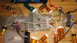
It is great to hear from you. Your remark inspired these thoughts. It connected, pills [e.g. Statins], addiction [ingested daily] and audio [promotes good health]. Addicted to audio is mostly diyaudio; which differs in meaning from audiophile. Come to think of it; life is one mother sum of countless addictions.I like those pill bottles. Addicted to audio
Best regards
This is it.
The attached diagram of the Acoustic Absorber is a practical device like that taught by Mr. Pass in his attendant patent. Note the following which also include recent improvements and simplifications:
Best regards.
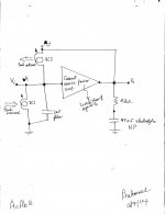
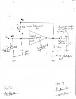
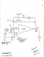
The attached diagram of the Acoustic Absorber is a practical device like that taught by Mr. Pass in his attendant patent. Note the following which also include recent improvements and simplifications:
- The schematic is the same as a phase inverting [operational] amp.
- Except that the voice coils [VC1 and VC2] of the subwoofer are the input and feedback elements instead of classical resistors.
- I removed the 0.33 Ohm degeneration resistors which appeared in the full-blown schematic of the amp in a previous post.
- Thus, this revised current source power amp [CSPA] operates at a certain maximum open loop voltage gain or transconductance [TBD].
- VC1 is bypassed with a 1uF film capacitor. This is a must to prevent oscillation. Higher cap values are not relevant.
- A Zobel [0.2 Ohm in series with 47 uF electrolytic] between the output Vo and common lowers output noise down to ~5 mVp-p; as seen on scope.
- Note the phase [shaded triangles] on the voice coils. These connections go with a phase inverting CSPA. This is the correct/right connectivity which enables the destruction of standing waves.
- The Acoustic absorber is stable [did not oscillate] when the leads of one voice coil were reversed relative to the other. But; it may augment rather than destroy standing waves which is contra to the desired objective.
Best regards.
Attachments
Testing The Acoustic Absorber
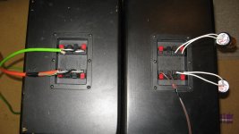
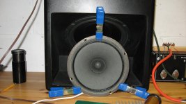
The Acoustic Absorber [AcAb] was tested as follows. Its subwoofer has a twin [I actually bought 3 such subwoofers at the time] which is fully operational; meaning I did not disable its commercial crossover network; like I had already done to the AcAb subwoofer. Both loudspeaker boxes were put on the floor with their loudspeaker drivers facing each other; like Kissing Gouramis, or mirror images. The attached picture is the testing setup, and shows the following.
Best regards.
The Acoustic Absorber [AcAb] was tested as follows. Its subwoofer has a twin [I actually bought 3 such subwoofers at the time] which is fully operational; meaning I did not disable its commercial crossover network; like I had already done to the AcAb subwoofer. Both loudspeaker boxes were put on the floor with their loudspeaker drivers facing each other; like Kissing Gouramis, or mirror images. The attached picture is the testing setup, and shows the following.
- The Right subwoofer is the intact twin. It is driven by a voltage source power amp [brown wire] fed by a signal generator. The pill tubes contain 8 Ohm power resistors. They attach to the satellite ports as loads.
- The Left loudspeaker is the AcAb subwoofer. The green cable goes to VC1 and is the "microphone". The red cable goes to VC2 and is the "speaker".
- Turn power on to the signal generator and set frequency at 50 Hz.
- Turn power on to voltage source power amp [VSPA]. It has a built in volume control which is ideal in this set up.
- The current source power amp [CSPA] in AcAb is not powered yet or is off.
- Put the leads of a scope between Vo [of CSPA] and ground.
- Advance the volume control on [VSPA] to energize the Right subwoofer [sound wave generator], and to simultaneously get a 400 mVp-p at Vo of CSPA. I had a standing wave at the cone of cone of AcAb, and vibrating it too.
- Measure also with the scope [Vi] which was 200 mVp-p.
- Now turn power on to CSPA.
- The new Vo as measured by the scope dropped to ~15 mVp-p. This was a roughly 26 fold reduction.
- The new Vi as measured by the scope diminished to ~7 mVp-p. This was roughly a 28 fold reduction.
- Points 8 and 9 said that sound pressure at the cone of AcAb is greatly dimished [a factor of ~27]. Or the parent sound wave impinging on the AcAb cone was effectively neutralized. This is how I see and explain via this test setup this invention by Mr. Pass.
- Points 8, and 9 also showed that the initial voltages at Vi and Vo were reduced together to ~zero volts; not one or the other. This system is not fighting itself, and both VCs are working together toward the same objective to null air pressure at the surface of their common cone.
Best regards.
Attachments
The proof is in the pudding
I listened to the songs Billie Jean [Jackson], Borderline [Madonna],and Sweet Dreams [La Bouche] to assess the performance of the Acoustic Absorber [AcAb]. The subwoofer of AcAb was put in the corner behind the Left speaker of the audio playback sysytem. The objective performance of AcAb was as follows:
I'll add more detail in a future post.
Best regards
I listened to the songs Billie Jean [Jackson], Borderline [Madonna],and Sweet Dreams [La Bouche] to assess the performance of the Acoustic Absorber [AcAb]. The subwoofer of AcAb was put in the corner behind the Left speaker of the audio playback sysytem. The objective performance of AcAb was as follows:
- To start, electrical power to the current source power amp [CSPA] in AcAb was not turned on.
- Attached the probes of a scope to Vo of CSPA; set at 5 mV per division.
- Played a song from the above set and watched the trace of the scope. It detected sine waves of various amplitude [up to 40 mVp-p] dancing on the screen. Clearly there was a detectable set of sounds across VC2.
- Turned on power to CSPA. The trace of the scope became flat at ~0 V. The set of sounds at the cone have practically disappeared; akin to the action of a notch filter.
I'll add more detail in a future post.
Best regards
Thank you. Any great sound system will soundeven better after taming/breaking up standing waves in the music listening space.Congratulations on a successful experiment.
Additional useful tests on Acoustic Absorber
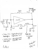
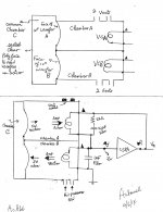
Hello. The attached picture shows two schematics for the Acoustic Absorber [dual voil coil subwoofer plus current source power amp; CSPA].
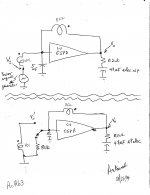
Hello. The attached picture shows two schematics for the Acoustic Absorber [dual voil coil subwoofer plus current source power amp; CSPA].
- The upper schematic uses the Acoustic Absorber as a phase inverting power amp having a voltage gain of 1. It is driven by a power signal generator at 50 Hz. It is stable, and has a pleasing 50 Hz signal hum.
- The bottom schematic allows the user to compare the performance of its stereo system with the Acoustic Absorber engaged or not. The mechanical toggle switch [at input] is at the remote listening chair/couch. It is connected to CSPA with a 20 foot three conductor cable. This was a round green power cable commonly used outdoors, and has the normal black, white and green conductors.
- Played a song [Rush by Paula Abdul] with the switch connected to the 8 Ohm input resistor. I noted the scope trace dance to the opening statement at Vo and Vi' [similar levels ~100 mVp-p].]. The switch was then connected to VC1. Replayed the start of the song and noted that both scope traces at Vo and Vi' were now at zero/flat baseline.
- The switch was encased in an opaque pill bottle, so that I will not be able identify position [VC1 or 8 Ohm]. Also, the scope was not used after this to detect [cheat] on the identity of its position.
- What power level requirement to this CSPA? I talked about ~100 milliVolt peak-to peak across a minimum 8 Ohm voice coils. Let's be conservative and use 1 Vp-p instead. This calculates to ~20 milliWatt.
Attachments
The attached diagram of the Acoustic Absorber is a practical device like that taught by Mr. Pass in his attendant patent.
Looking at it, I am unsure that you are not simply using the feedback to
freeze the motion of the cone. It looks like when a positive pressure is
applied, the result is negative voltage on the sensing coil which is then
inverted and amplified to a secondary coil, causing a force to push the cone
against the incoming pressure.
It might work (I'm uncertain) if you reverse the phase, but that would tend
to oscillation, I think>
I suggest that you consider two woofers in separate enclosures but close
next to each other instead of two voice coils on one woofer, and use a
non-inverting amplifier (or reverse the wiring of one of the coils).
Thank you Mr. Pass for your constructive comments. Your analysis in the first paragraph makes complete sense. It is an elegant explanation of the observed result of no sound. I will show another schematic which uses the identical components whereby the cone does not freeze; but continues to vibrate to put out an inverted acoustic signal.Looking at it, I am unsure that you are not simply using the feedback to
freeze the motion of the cone. It looks like when a positive pressure is
applied, the result is negative voltage on the sensing coil which is then
inverted and amplified to a secondary coil, causing a force to push the cone
against the incoming pressure.
It might work (I'm uncertain) if you reverse the phase, but that would tend
to oscillation, I think>
I suggest that you consider two woofers in separate enclosures but close
next to each other instead of two voice coils on one woofer, and use a
non-inverting amplifier (or reverse the wiring of one of the coils).
Reversing phase [second paragraph] caused an incurable oscillation as you expected.
I will gladly pursue your suggestion of the 3rd paragraph. More food for thought.
Todate, my "assemblies " are capable of only three possible outcomes. Oscillation, and cone freezeup are not the answer to the standing wave problem. The third outcome is for the assembly to generate an inverted acoustic signal of a certain controlled level.
Best regards.
Thank you for your continued guidance. Figure 4 in the patent shows a condenser [electret] microphone [22] requiring a bias voltage as the working example. Its additional small size allows for flexible positioning "preferably one inch forward of the base of the speaker cone"; but no more than 3 inches to prevent oscillation.Little electret microphones are quite inexpensive.
I have more therapeutic work to do on this diy.
Kind regards.
Thank you Mr. Pass for your guidance and suggestions; including the bolded one above. It enabled the assembly to work as taught in your patent, and it did not cause oscillation. I'll detail in a future post.Looking at it, I am unsure that you are not simply using the feedback to
freeze the motion of the cone. It looks like when a positive pressure is
applied, the result is negative voltage on the sensing coil which is then
inverted and amplified to a secondary coil, causing a force to push the cone
against the incoming pressure.
It might work (I'm uncertain) if you reverse the phase, but that would tend
to oscillation, I think>
I suggest that you consider two woofers in separate enclosures but close
next to each other instead of two voice coils on one woofer, and use a
non-inverting amplifier (or reverse the wiring of one of the coils).
Best regards.
I think you have this reversed. Pressure which pushes the cone in, met with
forces which push the cone out, will result in greater pressure.
We want zero pressure, practically speaking, reduced pressure.
The above Post #10 was by Mr. Pass. The underlined is not the teaching of his patent; which was my mistake. The following is the correct answer.
- But first, picture AcAbAmp1 shows the schematic of the current source power amp [CSPA]; absent its connections to the subwoofer voice coils.
- Most important is the inclusion of the degeneration resistors [0.33 Ohm] which are used to prevent oscillation [buzz].
- Picture AcAb4 shows the assembly diagram of the Acoustic Absorber [AcAb].
- Most important to note is the phase marker [solid triangle] of VC2 in relation to the phase marker of VC1. The leads of VC1 and VC2 marked with the triangle are joined together and generate input signal Vi.
- Here is the explanation of how AcAb works.
- By example, high air pressure pushes the cone inward. Both voice coils develop input signal Vi.
- Amplified and phase inverted signal Vo is applied to VC2 such that it further pulls the cone inward. This is the mechanism by which the incoming high air pressure is reduced by this instantaneous vacuum created by the cone being sucked in further. This is the same explanation as on page 4 in the paragraph of lines 13-28.
- This is a hypothesis. I added an independent single woofer at Vo [note phase] which may sit at the ceiling corner above the dual voice coil subwoofer. And/or at either corner [ceiling or floor] of the same wall shared by the subwoofer. The thought is that air pressure at the four corners are correlated [similar baro values of push or pull air pressure], and thus maybe treated as hypothesized.
Attachments
Update
The attached diagram shows a method to simultaneously treat four corners of an attendant wall for undesirable standing waves. This wall is behind the loudspeakers playing music. I am looking at it. Here are the details in the diagram:
The attached diagram shows a method to simultaneously treat four corners of an attendant wall for undesirable standing waves. This wall is behind the loudspeakers playing music. I am looking at it. Here are the details in the diagram:
- Sub A has dual voil coil [DVC] driver. It sits atop a pedestle [two idle loudspeakers] and is ~2 feet from the Right Ceiling corner.
- Sub B also has a dual voil coil [DVC], and is a twin of Sub A. It sits atop a pedestle [two idle loudspeakers] and is ~2 feet from the Left Ceiling corner.
- Sub A and Sub B [commercial] have their internal 2-way crossover networks connected or intact.
- Bookshelf loudspeaker A is an ADS L300C [commercial and intact]. It sits on the Right floor corner.
- Bookshelf loudspeaker B is the twin of ADS L300C bookshelf loudspeaker A. It sits on the Left floor corner.
- It is reasonable to believe that the phase and air pressure of the standing waves at the four corners are similar, and thus can be treated [disrupted] simultaneously with one current source power amp [CSPA].
- In the absence of music, the listening room was calm, quiet and induced relaxation.
- With music, its soundstage was broad, elevated and spacious with a discernible depth to it; but still inside the room .
- Surprisingly, low level info in music emerged as if it was new. Where was it all that time?
Attachments
Summary, and heads up
Todate, we have the blueprint of the proposed diy Acoustic Absorber, as I detailed it in the last 2 posts.
Todate, we have the blueprint of the proposed diy Acoustic Absorber, as I detailed it in the last 2 posts.
- An amplifier which uses readily available low cost components. It is stable; meaning it does not buzz or sing.
- An enclosed dual voice coil subwoofer. It can be one's diy or available commercially; with or without a crossover network.
Mr. Pass wrote....
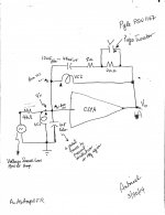
"In the meantime, keep building amplifiers." This is the last sentence in his article 'SONY VFETs in Push-Pull Class A Part1:...' Has anyone ever heard the performance of an amplifier system which operates by using loop positive feedback [PFB] instead of the classical NFB? I confess; yours truly, and I assure you it is not oscillation. This DIY [posts #34 and onward] implicitely describe such a system using loop PFB to satisfy or faithfully represent this invention by Mr. Pass. A system which otherwise uses loop NFB fails the invention, or doesn't cut it. The attached picture shows the schematic of this full range amplifier system. Here are its details:
I 'll post a picture of this amp system.
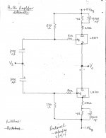
"In the meantime, keep building amplifiers." This is the last sentence in his article 'SONY VFETs in Push-Pull Class A Part1:...' Has anyone ever heard the performance of an amplifier system which operates by using loop positive feedback [PFB] instead of the classical NFB? I confess; yours truly, and I assure you it is not oscillation. This DIY [posts #34 and onward] implicitely describe such a system using loop PFB to satisfy or faithfully represent this invention by Mr. Pass. A system which otherwise uses loop NFB fails the invention, or doesn't cut it. The attached picture shows the schematic of this full range amplifier system. Here are its details:
- CSPA is the same as noted earlier[post #34].
- The voce coils VC1 and VC2 belong to an enclosed 10" dual voice coil driver lacking a crossover network; as previously reported .
- The Zobel network across VC2 suppresses high frequency oscillation in the high KHz range. It is also an improvement over the older Zobel of 47 uF in series with a resistor [0.2 Ohm] from Vo to ground; e.g. in post #34. This improvement shows itself as a clean [Vo] sine wave to beyond 10 KHz.
- The voltage drop across the Zobel resistor [20 Ohm] drives a piezo tweeter.
- I have/found flexibility in choosing the values of the Zobel capacitors [10 uF to 47 uF] and the values of its resistors to splice the sound of the drivers for the best fit or balance.
- The phase of the voice coils as shown enables loop PFB.
- A low power voltage source amp [generator] develops an input signal Vi. Its magnitude during play music reaches ~ 100 mVp-p.
- Ignore the generator for Vi. The system is still an acoustic absorber which is faithful to the invention. Meaning; an "acoustic Vi" can be independently generated from standing waves in room corners to be destroyed.
- So, I have an amplifier system [uses loop PFB] which simultaneously plays broadband audio, and suppresses standing waves when/if put in a corner of a room.
- The resistor [47 Ohm] connected to the generator of the "musical Vi" is high enough in value so as not to diminish the magnitude of the acousic Vi needed to destroy standing waves.
- The value of the resistor [47 Ohm] can be decreased . I used 2 Ohms for comparison. Note that at 2 Ohms, the low output Z of the generator will shunt the acoustic Vi to a greater extent, and thus may disable the invention.
I 'll post a picture of this amp system.
Attachments
More refinements
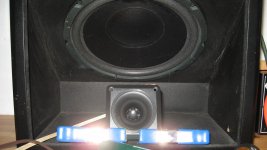
The Acoustic Absorber continues to be versatile in its scope of use. I refined it further from the previous post as shown in the attached diagram:
The Acoustic Absorber continues to be versatile in its scope of use. I refined it further from the previous post as shown in the attached diagram:
- Eliminated the piezo tweeter.
- Note the Zobel across VC2. It is an 0.1uF film capacitor in series with a resistor valued at 28 Ohms. A resistor of standard value equal to 27 or 33 Ohm will do fine instead.
- This Zobel and the 1uF film across VC1 effectively eliminate an oscillation is the high kiloHz region.
- I added a loudspeaker load [Zl] at Vo.
- The second attached picture shows an example of this loudspeaker [Zl] which is an 8 inch paper woofer cone/whizzer [8 ohm, 5W and ~full range range].
- Note that I did not assign a phase symbol to this driver relative to that of the VC1 and VC2. One connection and its reverse sound different; both of which are fully satisfactory.
- Another example of the loudspeaker Zl is a 4 Ohm two-way from Boston mobile audio model SE75 [un-enclosed 4 inch rectangular].
- Sounded damn good like the 8 inch driver either way of connection of its leads.
- I attributed the two different sounds due to an interaction [augmentation or cancellation] between Zl and the dual voice coil subwoofer which has an audible output into the voice spectrum in the absence of Zl.
- Note both Zl drivers radiate from their front and back cone surfaces. Per the patent, their backwave is/can be easily cancelled so as to improve their bass performance.
Attachments
Acoustic Absorber comprising Jensen Bandpass Subwoofer [JBS]
JBS is a dual 4th order bandpass system using two ten-inch woofers [electrically independent] which are mounted in a 3 chamber arrangement. The impedance of each voice coil is 4 Ohms. JBS was designed for use in vehicles with one of its sides made of a clear plastic so as to show off its drivers; in action and not. The top part of the attached picture shows an illustration of JBS:
JBS is a dual 4th order bandpass system using two ten-inch woofers [electrically independent] which are mounted in a 3 chamber arrangement. The impedance of each voice coil is 4 Ohms. JBS was designed for use in vehicles with one of its sides made of a clear plastic so as to show off its drivers; in action and not. The top part of the attached picture shows an illustration of JBS:
- A sealed common chamber [C] has the clear plastic side. One notes the frontside of the cones of the woofers which are laid down side by side.
- The backside of Woofer A [10"] resides in its own chamber [A] which has two ports or vents.
- The backside of Woofer B [10"] resides in its own chamber which also has two ports or vents
[*]The three chambers [A, B, and C] are coupled to each other by the cones of the drivers.
- The amp CSPA, the Zobel [0.1 uF in series with 27 Ohm] , and 1 uF at Vi are held constant as previously used.
- This arrangement gave a stable amp; no buzz or whistles.
- The ports/vents of the upper chamber [A] were sealed.
- I'll show a picture of JBS and the method I used to block the vents.
- A standing wave [SW] builds up air pressure at the open ports of chamber B.
- This air pressure [AP] transfers to the inside of chamber B.
- This [AP] pushes on the backside of woofer B [slim arrow] , and moves its cone forward towards chamber C which is air tight or sealed.
- The forward motion of woofer B [now acting as a microphone] generates an input signal Vi to CSPA. Note its phase.
- The forward motion of woofer B due to [AP], builds air pressue in chamber C.
- The rise in air pressure in chamber C [transferred from chamber B] pushes on the cone face of woofer A.
- Thus, the cone of woofer A moves towards the insides of its chamber A
- The fun begins as input signal Vi is amplified, inverted and applied [properly] to the voice coil of woofer A.
- Properly means the phase of the electrical signal Vo in relation to the lead of woofer A marked with a solid triangle.
- The electrical energy from CSPA is dissipated in woofer A and forces it to suck-in its cone towards the inside of its sealed chamber A [heavy arrow in chamber A].
- Consequently, the action of woofer A creates a transient vacuum in sealed chamber C.
- The vacuum in chamber C next forces the cone of woofer B to move forward towards it.
- The forward movement of woofer B towards chamber C creates a vacuum in its own chamber B [heavy arrow].
- The initial high air pressure from SW and the resultant low pressure [vacuum] happen simultaneously in chamber B. They neutralize each other; partially or fully.
- Neat!
Attachments
- Home
- Amplifiers
- Pass Labs
- DIY the device of US Patent 4,899,387