I know I'm a latecomer here to the Pearl 2 project, and I have searched pages here for any help on my particular problem, and can't find any info.
Here goes. I ordered the boards from Pass. I ordered the parts from Mouser.
I, like 6L6's posts already had a 30v+30v at 250 VA Avel Lindberg transformer. I took the lead from 6L6's posts and used dropping resistors between 10,000 uf caps, to lower the v+ and v- rail voltages from +/- 46 to about +/-34 volts to the regulators. Through trial and error, I found 200 ohms for v+, and 300 ohms for v-. V+ drops nicely from 46 to 33 vdc. The 7824 outputs a nice + 24 vdc.
V- doesn't drop at all, stays at 46 vdc. Although the output of the 7924 is a nice -24vdc.
I measured the current through the dropping resistors. I read about 58 milliamps through the positive. Absolutely no current flow through the negative dropping resistors. I am hoping someone ,may have had similar, and found the solution. I first thought I had installed the bias LED'S backwards, but the are oriented according to the board symbol.
I have read many have had problems with the ZVP3310. could that cause zero negative current to be drawn from the supply?
Any help would be wonderful, and very much appreciated.
Thanks,
mg16
Here goes. I ordered the boards from Pass. I ordered the parts from Mouser.
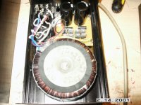
I, like 6L6's posts already had a 30v+30v at 250 VA Avel Lindberg transformer. I took the lead from 6L6's posts and used dropping resistors between 10,000 uf caps, to lower the v+ and v- rail voltages from +/- 46 to about +/-34 volts to the regulators. Through trial and error, I found 200 ohms for v+, and 300 ohms for v-. V+ drops nicely from 46 to 33 vdc. The 7824 outputs a nice + 24 vdc.
V- doesn't drop at all, stays at 46 vdc. Although the output of the 7924 is a nice -24vdc.
I measured the current through the dropping resistors. I read about 58 milliamps through the positive. Absolutely no current flow through the negative dropping resistors. I am hoping someone ,may have had similar, and found the solution. I first thought I had installed the bias LED'S backwards, but the are oriented according to the board symbol.
I have read many have had problems with the ZVP3310. could that cause zero negative current to be drawn from the supply?
Any help would be wonderful, and very much appreciated.
Thanks,
mg16
Pearl 2 problem
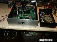
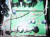
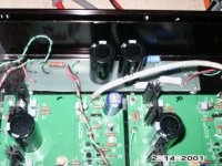
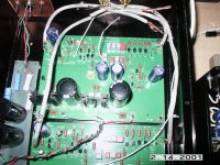
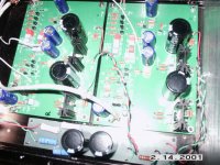
Input, outputs and tt ground lines are not connected yet.
Pics not great, but the best I can get with my old camera.
Input, outputs and tt ground lines are not connected yet.
Pics not great, but the best I can get with my old camera.
Attachments
first thing - using RC element for wasting voltage/dissipation is good praxis only if you have enough mileage to exactly know what you're doing ; if that's not the case , zener folowers are way to go , or any other active way of voltage (pre)regulation ;
second thing - I'm lazy to search for schematics in my PC , and majority of us old farts are too , so please post schematic with (your exact) voltages for main critical points
second thing - I'm lazy to search for schematics in my PC , and majority of us old farts are too , so please post schematic with (your exact) voltages for main critical points
Pearl 2 Help
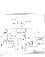
Found Wayne's voltage map, and recorded my measurements.
Hope its readable.
My readings using a DVM:
PAD1=+34.1 VDC
U1 PIN 3 = +24.1 VC
Q1 EMITTER = +20.12 VDC
VOLTAGE ACROSS R6= 0 VDC
Q3 BASE = +9.5 VDC
Q3 COLLECTOR = +10.3 VDC
Q3 EMITTER = +8.83 VDC
Q9 PIN 3 = +.0495 VDC
Q4 DRAIN = .003 VDC
PAD7= -43.6 VDC
R28 TO C24 - TERMINAL = -23.95 VDC
Q10 EMITTER = -23.94 VDC
LED1 ANODE = -23.34 VDC
R17/R16 JUNCTION = +.026 VDC
Q11 EMITTER = -23.94 VDC
Thanks,
mg16
Attachments
Pearl2 Help.
Had I known the exactly, (or even a close aprox. of the total current drawn by the Pearl 2), it would have been easy to calculate the dropping resistors needed in order to lose the 12 volts excess from each supply provided by my transformer. Simple ohms law.
As it was, I could only find a vague reference to the circuit using about 100 milliamps, and that the negative supply drew somewhat less than the positive. It really wasn't definitive enough to accurately calculate the actual resistance needed for each rail. Taking a wild stab in the dark at 60/40 positive current vs negative, I calculated 200 ohms/.72 watt positive rail , (used a 5 watt on hand), And 300 ohms .5 watt negative rail, (also used a 5 watt on hand.)
But I'm at a loss why negative current isn't flowing.
mg16
Its Alive!
The old advice about having an impartial observer look at your work, holds true. Something so simple as forgetting a resistor in the bias circuit ,was overlooked by me, in my haste to listen.
I installed the R25'S, and the on board led's lit. The power supply rail are in spec, and voltage points within the circuit measure correctly.
I will have to connect my inputs, outputs, and TT grounds up later, and give it a listen, but it all looks very promising.
Thank you Zen Mod, and Omishra. I hopefully will remember to slow down and triple check everything next project.
mg16
Attachments

")
Pearl 2
Thanks for all the help.
Finally got it finished last night. Adjusted the dropping resistors to 150 ohms/5W on the positive rail, and 300 ohms/5W on the negative. Regulators now fed by +- 34 volts. Wired up the inputs and outputs with good shielded cable, hooked it into my system and played a few records with some Wild Turkey Rye Whiskey on the rocks. Played Fleetwood Mac "Tusk" . Plenty of clean detail, black background, very quiet, soundstage beyond the speaker boundary's, bass a little light, but was solid enough and adequate. Stevie Nicks and Christine McVies voices conveyed tons of emotion. Made me want to sit and listen, and not get up until the albums was over. Played several more albums, including Van Halen "Fair Warning", and some old Garage band 60's stuff, Shadows of Night "Gloria" LP, and "The Swamp Rats". It all sounded great. Definitely a keeper. I would recommend anyone thinking of building it, to jump in and do it.
Thanks,
mg16
- Status
- This old topic is closed. If you want to reopen this topic, contact a moderator using the "Report Post" button.
- Home
- Amplifiers
- Pass Labs
- Pearl 2 help?