Dimtri,
You can find the writeup and PCB files here:
The Zen Headphone Amplifier | HeadWize
http://headwize.com/download/pellerano_pcb.zip
Cheers,
Dennis
You can find the writeup and PCB files here:
The Zen Headphone Amplifier | HeadWize
http://headwize.com/download/pellerano_pcb.zip
Cheers,
Dennis
Hello
I downloaded pdf files of pcb, from HeadWize, and I printed it, but when I compare pcb overlay, and bottom, it seems like a bottom pdf file needs to be mirrored.
For making my own pcb I use laser print method, so am I right, do I really need to mirror bottom pdf.
Thanks.
I downloaded pdf files of pcb, from HeadWize, and I printed it, but when I compare pcb overlay, and bottom, it seems like a bottom pdf file needs to be mirrored.
For making my own pcb I use laser print method, so am I right, do I really need to mirror bottom pdf.
Thanks.
power supply
another question.
is there any other solution of power supply?
i like this one from 19th page , post 181.

SolvedHello
I downloaded pdf files of pcb, from HeadWize, and I printed it, but when I compare pcb overlay, and bottom, it seems like a bottom pdf file needs to be mirrored.
For making my own pcb I use laser print method, so am I right, do I really need to mirror bottom pdf.
Thanks.
another question.
is there any other solution of power supply?
i like this one from 19th page , post 181.
Question about the Muting Timer Circuit
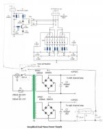
I would like to retain the muting timer function, but would like to eliminate the voltage divider network (2 x 220R) that is used to create the 12V for the relay, and also switch off the line voltage coming into the transformer when the headphone amp is not being used.
Would the modified circuit shown below accomplish this? The reason I want to do this is to keep all AC out of the unit when I am sharing the input select and volume control to act as a passive preamp for non-headphone use.
Thanks!
Attachments

Dimtri,
You can find the writeup and PCB files here:
The Zen Headphone Amplifier | HeadWize
404 Not Found
Cheers,
Dennis
Do you or anyone have the write up and pcb files, as the headwize site is no longer available. If you have the said items please can you send me to my mail: mamun.nj@gmail.com
I am so eagerly trying to get those materials.
Thanks.
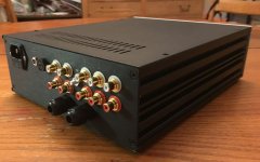
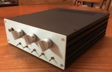
Thanks for sharing the design of your headphone amp Tortello! Mine is up and running and sounds great through my Grado SR325e headphones. Thanks also to everyone else who posted pictures of their builds and shared their experiences it really helped me.
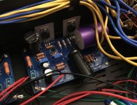
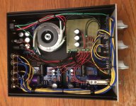
To help others with future builds I am posting a couple pictures and some of my learnings (If these things are obvious to some, please keep in mind that this is my first DIY electronics project).
Observations:
1) This amp sounds really good!
2) Using high quality audio specific input and output coupling capacitors made a noticeable increase in the sound quality.
3) Matching the Mosfets and biasing the amp was much easier than I though it would be.
4) After listening for the power on/off thump, I did not feel the need for the muting circuit. Power on has a quiet thump, and power off had no thump, just a fading away as the capacitors drained. (My power switch is between the line voltage and the transformer.)
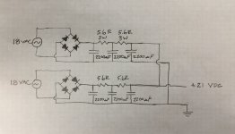
5) The hardest aspect of my build was getting the power supply quiet.
Two things really quieted my amp down:
Adding some additional CRC filtering resistors to my power supply
capacitor bank (see power supply sketch below)
Adding Tortello's recommended 100 ohm resistor between the output
ground and the safety earth.
Without these two items, I had a very annoying 60Hz buzz. After, I could not hear any power supply noise whatsoever.
6) The parallel 470 uF output coupling capacitors can be replaced by a single 1000 uF Nichicon Muse capacitor (P/N UKZ1E102MHM) for less money, and I liked the idea of having a single vs. multiple caps on the output.
Thanks again Tortello!
PS: It did take a fair amount of effort to find Tortello's excellent build guide, If you read this Tortello, maybe you could post the build guide, schematics etc. here so we don't have to rely on the web archive link above?
To help others with future builds I am posting a couple pictures and some of my learnings (If these things are obvious to some, please keep in mind that this is my first DIY electronics project).
Observations:
1) This amp sounds really good!
2) Using high quality audio specific input and output coupling capacitors made a noticeable increase in the sound quality.
3) Matching the Mosfets and biasing the amp was much easier than I though it would be.
4) After listening for the power on/off thump, I did not feel the need for the muting circuit. Power on has a quiet thump, and power off had no thump, just a fading away as the capacitors drained. (My power switch is between the line voltage and the transformer.)
5) The hardest aspect of my build was getting the power supply quiet.
Two things really quieted my amp down:
Adding some additional CRC filtering resistors to my power supply
capacitor bank (see power supply sketch below)
Adding Tortello's recommended 100 ohm resistor between the output
ground and the safety earth.
Without these two items, I had a very annoying 60Hz buzz. After, I could not hear any power supply noise whatsoever.
6) The parallel 470 uF output coupling capacitors can be replaced by a single 1000 uF Nichicon Muse capacitor (P/N UKZ1E102MHM) for less money, and I liked the idea of having a single vs. multiple caps on the output.
Thanks again Tortello!
PS: It did take a fair amount of effort to find Tortello's excellent build guide, If you read this Tortello, maybe you could post the build guide, schematics etc. here so we don't have to rely on the web archive link above?
Attachments
Good job!
Yes, I agree with you, you have to use quality capacitors at the input and especially at the output and yes, with matched transistors the work is very easy.
I used a large CRC filter, with Grados my amp hasn´t noises but with extremely sensitive headphones (like JVC PX1000) you can hear a very low hum (I need to try a 100R between ground output and earth ground).
I have two 1000uF KW Nichicon on the output and I feel very happy with the sound.
Dear,
I dearly like to build this amp but i am really new to this field with very little knowledge about building this kind of amplifier. May I ask your help building this amp please? I need the details write ups including schematic diagram and other necessary information of the build. Could you kindly send me these things to my mail? My mail address is <mamun.nj@gmail.com> Thanks once again.
Mamun
The link in post 209 of this thread is the easiest way to get the information you are looking for. You can also google "zen headphone amp kit" and you will get hits for partial instructions, and from people selling kits on ebay and amazon (I have not idea if they ship to Bangladesh). I bought a "kit" and the circuit boards were good (verified vs. the schematic in Tortello's instructions), but the components were mostly counterfeit. I bought all of my components from Mouser, Digikey and some audio specialty shops and I am glad that I did.
Hi,
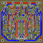
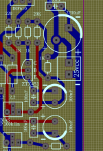
Because I was curious to build this headphone amplifier, I made a PCB (second) variant more compact.
The first one was 12 x 12 cm and had some mistakes. It is not an original version but adapted after the others that have been proposed by various members.
The prototype, in a single layer, is still on the work table, not having too much time for it.
The first impression is ok and thanks to the member @tortello and to the others who participated directly and indirectly in this project with tips and proposals.
Attachments
Hi,
Interested in your layout.
Also tried to make a single pcb for the whole amplifier (power+amplifier), maybe I should post it for advices. It was aside for years. The main problem is that there is a strong noise even with the inputs not connected (no wires). Might cut the board to separate power and amplifier parts.
")
- Home
- Amplifiers
- Pass Labs
- ZEN-like headphones amp