R8 is 1K
I change the LSJ74 I bought to DIY Audio for replacement and all solved !!!
Thanks for your support ZEN now is sounding perfect !! Maybe yesterday with 4ohm monitor was suffering... who knows.... I'm in love with your recommendation of preamp + B1 buffer.... now listening Agnes Obel perfect !!!
I change the LSJ74 I bought to DIY Audio for replacement and all solved !!!
Thanks for your support ZEN now is sounding perfect !! Maybe yesterday with 4ohm monitor was suffering... who knows.... I'm in love with your recommendation of preamp + B1 buffer.... now listening Agnes Obel perfect !!!


when I built my Aleph J, I built it with balanced inputs but have only been running it with the RCA inputs. If I ran it to the balanced inputs from a balanced source, would that cancel out the second harmonic of the amp, or is it what it is no matter the inputs?
Thanks in advance,
Alan
Thanks in advance,
Alan

Still enjoying the Aleph J! ��
One thing I noticed is sort of a double thump to the speakers when I turn it OFF, but hardly anything when it is turned on. Of course, done in the correct order : amp off first when shutting down, and vice versa when starting up.
Is there any harm that this could pose to components or speaker?
One thing I noticed is sort of a double thump to the speakers when I turn it OFF, but hardly anything when it is turned on. Of course, done in the correct order : amp off first when shutting down, and vice versa when starting up.
Is there any harm that this could pose to components or speaker?
I had the amp running for over 200 hours and decided to replace R7 and R27 with a fixed resistor. The offset and bias were rock solid. While I had the amp boards out, I wanted to take care of a few things on the power boards - like get them hardwired to the amps boards.
Heres what I did:
Power supply boards - from diyaudio
replace 3k bleeder resistor to 10K
replace 5K LED resistor to 10K
remove outbound snubber capacitor
remove outbound snubber resistor
remove euroblocks and hardwire connections
On the amp boards from diyaudio:
remove R8 and replace with 1K ohm resistor
remove R7 and replaced with appropriate resistor
remove R27 and replaced with appropriate resistor
replace LED resistors with 10K resistor
After getting everything buttoned up I had some issues. The fixed resistors didn't give the results I was hoping for - offset and bias were off. Things were so far off, Q5 and Q7 smoked a bit on one amp and turned the 0.47 resistor, on the other channel, brown that it was so hot. I replaced the pots, but no good.
Once the pots were back in and powered it back up, the offset was 5V at minimum and bias was high at partial. I powered up using a variac and could only get to 40% before offset went to 15 and bias tried to run over 1V. I shut everything down.
I tested power supply voltage before connecting to the amp board, 25.3 for both + and -. The - side ran anywhere from 1 to 7 lower that the + once connected back to amp boards. The negative side also takes about 10 minutes to drain caps, the + about 30 seconds.
Maybe I've been looking at this too long and have overlooked da simple mistake. TIA for any insight into the problem.
Problem solved. D1 tested bad, replaced, and all is good.
Still enjoying the Aleph J! ��
One thing I noticed is sort of a double thump to the speakers when I turn it OFF, but hardly anything when it is turned on.
I have 3 pairs of AJ, and all do the same.
3U heat sink possibility
I picked up a pair of Altec Lansing 1407A amplifiers. These are low end PA amps. They have no hifi value, however the chassis are in great shape and the power transformers are the right specs for the Pass amps. $100 for 2 chassis and transformers, hard to pass on.
The only issue I see building an Aleph J into them is that they are 3U. Is it possible to do this without adding fans? I currently have the Aleph J running in a DIY audio 5U chassis and it never really gets that hot.
Is using a different heatsink as easy as matching the total surface area specs of the DIY heatsinks? Same surface area and thermal resistance?
Would a F5 or F6 work well in a 3U?
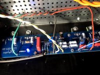
Hi all. I finished my Aleph J this weekend, but need some help. I think my left channel is not doing perfectly well. Though I risked to connect the speakers and music sounds fantastic.
On start up, the voltage on the left channel R18 is as high as 580mV and then gradually goes down until it settles to 406mV in about 30 minutes. The right channel starts on 400mV and stays on 412mV in 30 min.
Also, Mosfets on the left channel are going a bit too hot. After 30 min. I have the following temperatures and votages on Q6, Q5, Q8, Q7 and R17, R16, R19, R18 respectively (I think Q5 and Q8 are too hot):
68C, 82C, 78C, 71C - 321mV, 500mV, 419mV, 406mV
While the right channel (that I think is perfecty ok) has this:
70C, 67C, 68C, 70C - 368mV, 331mV, 306mV, 399mV
Also, the trimpot on the left channel is all the way clockwise to the end (I could not increase the bias current any more if I would need that). Vertical R27 is jumpered.
R6, R30 are also jumpered.
Heatsinks are at 40-43C (the left one is naturally a bit hotter).
DC offset on the outputs is perfecty fine: starts at 20mV and goes down to 2mV in 30 min.
D1 has 9.12V accross it, R8 is 1kOhm and has 8.55V accross.
What hot mosfets can hint to? Could it be oscillation? My experience is quite short in electronics, never had faced oscillation before, so I have no idea.
I bought all the mached JFets and all Mosfets from the diyAudio store.
Also I attach the picture of the faulty channel.
Any hints what could be the problem would be highly appretiated.
-Alvis
Attachments
you know that you need them matched in pairs?
so - two pairs for channel, one pair going in upper rail, second pair going to lower rail
from your well made table of voltages across Rs , I believe you can make combination to have 4 proper pairs, then relocate them as needed
for instance - one pair 306 and 321mV etc.
of course, only proper matching process could give you certain info ........
I don't know how mosfets from Store are delivered, but is there possibility that you unintentionally mixed them, prior to mounting?
not trying to do any apologetic business here for Boyz'n'Girlz from Store, but - considering how they're paid big money for all work, I believe we owe them some slack and no hard feelings
anyway , if it ends as their mistake, I'm sure it'll be solved as it needs to be
Thanks for you comment, Zen Mod.
The thing is that all 8 mosfets from diyAudio store came in one plastic bag, so I assumed that all of them are well enough matched between them (otherwise what sense would it make if I should be re-matching them myself?). Perhaps my thinking was wrong. But here I am now. Also, there were no markings of them (like IDs from the maching process as in the picture in the store page), but then again, you can put IDs on paper rather than on the mosfets themselves when matching them. Ok, perhaps I will politely ask the guys in the store.
Anyway. I could try to re-match them as you said - based on the voltages that I see. But that would mean a lot of desoldering (prone to some damaged traces etc...) and I would also have to buy new thermal insulation for them (mine was sticky, so I would ruin it when taking the boards away from the heatsinks).
What if I use it as it is? What could be the consequenses of the mismached mosfets like that? Bigger distortion? Shorter life of mosfets?
Could there be other reasons than mismached mosfets in my case?
Thanks
-Alvis
It's Sticky thermopad 20x130x2mm 6 W/mK (was exactly the size I needed for 8 mosfets).
I bought it locally here:
Sticky thermopad 20x130x2mm 6 W/mK
Heatsinks do get to ~50C during the continous use, so I suppose it's thermal conductivity is fine.
I bought it locally here:
Sticky thermopad 20x130x2mm 6 W/mK
Heatsinks do get to ~50C during the continous use, so I suppose it's thermal conductivity is fine.
Last edited:
- Home
- Amplifiers
- Pass Labs
- Aleph J illustrated build guide