Hi guys...A big question...before starting to fix PCBs on the metal case I've tried to see if all is working (amp never switched on before). The problem was that after few seconds final FETs were untouchable (high temperature). That's ok ('cause I'm not still using any heatsink) or there is something wrong? Of course I've still to set bias and offset...
I consulted with a Real EE before powering up my First Watt M2 without heatsinks. He identified two resistors on the board, whose values should be increased by 100X. This decreased the output stage bias current (and output stage POWER) by 100X, allowing me to run the amplifier without bolting the output transistors to big mama heatsinks. I was able to apply sine waves in and observe sine waves out [NOT into 8 ohm loads of course!]. In other words: the board worked! I was able to do this before final, painful to reverse, mounting on the heatsink.
Maybe you can find a Real EE to suggest some kind of a similar plan on this First Watt amp, so you can run it with no heatsinking at all and verify that it's hooked up correctly. That it operates as an amplifier.
Maybe you can find a Real EE to suggest some kind of a similar plan on this First Watt amp, so you can run it with no heatsinking at all and verify that it's hooked up correctly. That it operates as an amplifier.
So you're saying on a First Watt M2X if we increase the source resistors (R13, R14) from .47R to 47R the circuit can operated and be tested without heat sinking?
I bet we could enlist someone proficient in spice to run models showing what resistors need to increase on the Aleph J...with or without an EE degree? I'm guessing R18 and R19.
Maybe you can find a Real EE to suggest some kind of a similar plan on this First Watt amp...
I bet we could enlist someone proficient in spice to run models showing what resistors need to increase on the Aleph J...with or without an EE degree? I'm guessing R18 and R19.
Be sure to solder the temporary 100X resistors in such a way that you can easily remove them later. When you replace them by the final resistors whose resistance and wattage rating match the designer's original schematic, you don't want to accidentally destroy or lift-off the copper pads on the PCB!
If the original, full power Class A design has a resistor which is (let's just pretend) 2.7 ohms & 10 Watts ... you could consider replacing it with a 270 ohm, 1/4 Watt resistor. Slide an insulating sleeve over each of the leads, 2 cm long, before stuffing and soldering. These nice long insulated leads can't short to other conductive items on the board or the test gear. The longer are the leads, the easier it will be to unsolder and remove the resistor without damaging the board. Grab the lead with needle nose pliers on the top side of the board, apply soldering iron to solder joint on bottom side of the board, pull gently.
Of course the more resistors you swap, the greater the danger of ruining the board. Here's the math:
If "p" is the probability of accidentally ruining the board at each individual resistor, and if each resistor solder/desolder operation is mathematically independent from all the others,
Then the probability of ruining the board when you solder/desolder "N" resistors, is
P_ruin(N) = 1 - [(1 - p)^N]
Example 1: p=0.01 and N=1. There is one resistor and the probability of getting it wrong is 1%. Then the probability of ruining the board is 1 - [(1 - 0.01)^1] = 0.01. Exactly as expected.
Example 2: p=0.01 and N=150. There are 150 resistors and for each one, the probability of getting it wrong is 1%. Then the probability of ruining the board is 1 - [(1 - 0.01)^150] = 0.779. Perhaps not as expected.
Of course the more resistors you swap, the greater the danger of ruining the board. Here's the math:
If "p" is the probability of accidentally ruining the board at each individual resistor, and if each resistor solder/desolder operation is mathematically independent from all the others,
Then the probability of ruining the board when you solder/desolder "N" resistors, is
P_ruin(N) = 1 - [(1 - p)^N]
Example 1: p=0.01 and N=1. There is one resistor and the probability of getting it wrong is 1%. Then the probability of ruining the board is 1 - [(1 - 0.01)^1] = 0.01. Exactly as expected.
Example 2: p=0.01 and N=150. There are 150 resistors and for each one, the probability of getting it wrong is 1%. Then the probability of ruining the board is 1 - [(1 - 0.01)^150] = 0.779. Perhaps not as expected.
Mark,
Even among nerds, this is the nerdiest post I`'ve ever read
") I had no idea I was flirting with disaster! I have to ask what you do for a living.
I had no idea I was flirting with disaster! I have to ask what you do for a living.I'm sure you've noticed that it is the exact same calculation, when you wish to compute:
The probability of getting at least one "100-year flood", over a span of 150 years, is 77.9%.
I'm a retired guy, living where my DIYA avatar icon says, enjoying the lack of stress which accompanies lack of employment and lack of commute.
What's the probability of NOT getting a "100-year flood," 150 years in a row? Answer: 22.1% (namely, 1 - 0.779).
I'm a retired guy, living where my DIYA avatar icon says, enjoying the lack of stress which accompanies lack of employment and lack of commute.
... enjoying the lack of stress which accompanies lack of employment and lack of commute.
Amen.
(I used to live in your neck of the woods: Willow Glen and then Alum Rock. Boy do I miss Chez Sovan and Krung Thai.)
I did live a bit further north, some years ago, in Belmont. Do miss it as well. When we moved there in 2002, the commute wasn't so bad generally, because the bursting of the telecoms and Internet bubbles wasn't that long before, with the attending, mostly negative consequences for the Bay Area, but the commutes got worse year after year .
Haven't really done a whole lot better regarding the commute since we moved to the Düsseldorf area.
Best regards,
Claas
. Haven't really done a whole lot better regarding the commute since we moved to the Düsseldorf area
. Best regards,
Claas
Willow Glen and then Alum Rock. Boy do I miss Chez Sovan and Krung Thai.)
Hope you were here during the glorious but all too brief lifetime of Dasaprakash. You might mourn, as I do, the death of Orchard Supply Hardware. Murdered by their newest and final owner, Lowes.
If you are planning to change resistors, there is a nice way to avoid damaging the board. This method also allows the resistor to be changed without removing the board. It is a trick I learned from a friend of mine who used to work in the electronics industry: Use a little solder support terminal.
The terminals are soldered into the pcb and the resistor (leads snipped short) is soldered to the terminal (from the component side). The terminals are also great to attach wires to the board (on the component side!) and to mount the 3W resistors used in FW amps (keeps the resistors slightly raised above the board which helps with heat).
I just ordered a few hundred at Buerklin in Germany. They are available in 2 sizes. Too bad they are only available tinned as they no longer stock the gold-plated models.
Standard 1493-11, tinned solder terminal | Burklin Elektronik
Thank you very much albertNL! That Bürklin component looks like a perfect match to Mouser part number 534-1035 which is on the shelf today, and costs $16.90 for a package of 100 terminals. Mechanical drawing below. The online catalog at Keystone Electronics's website shows about a dozen variants in different sizes etc.
_
_
Attachments
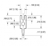
Thank you very much albertNL! That Bürklin component looks like a perfect match to Mouser part number 534-1035 which is on the shelf today, and costs $16.90 for a package of 100 terminals. Mechanical drawing below. The online catalog at Keystone Electronics's website shows about a dozen variants in different sizes etc.
_
That is funny. I wanted to order some from Mouser because I did not have any left. I could not find them and even emailed Mouser support a photo but they could not help without a part number (which I did not have). [Now I do haha.]
Buerklin is cheaper than Mouser but has the disadvantage of freight costs. Luckily I have family visiting from Germany next month, so low shipping costs
Most of the people who are Black Belt users of Mouser's website, are Mouser customers rather than Mouser employees. I'm not shocked that Mouser was unable to find a part on their own site ... searching for parts, after all, is not their primary job.
This particular one is made by Keystone, who tends to charge more than other manufacturers. I wish we could find the same thing made by Harwin, who tends to be noticeably cheaper than Keystone. But I haven't found anything yet.
This particular one is made by Keystone, who tends to charge more than other manufacturers. I wish we could find the same thing made by Harwin, who tends to be noticeably cheaper than Keystone. But I haven't found anything yet.
Most of the people who are Black Belt users of Mouser's website, are Mouser customers rather than Mouser employees. I'm not shocked that Mouser was unable to find a part on their own site ... searching for parts, after all, is not their primary job.
"Black Belt users" Well said, and in a funny way.
This grasshopper has much yet to learn of the Mouser Mysteries.
Great tip on building so resistors are easily swapped.
Simple and effective - excellent. Thanks, Albert.
Thanks for the idea.If you are planning to change resistors, there is a nice way to avoid damaging the board. This method also allows the resistor to be changed without removing the board. It is a trick I learned from a friend of mine who used to work in the electronics industry: Use a little solder support terminal.
Standard 1493-11, tinned solder terminal | Burklin Elektronik
Tell me, how to put a trimmer (pot) on the board instead of a constant resistor 1/4 W? Perhaps there is a solution similar to yours.
Perhaps there are transition panels. Help solve the puzzle.
Correct waveforms?
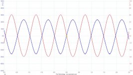
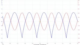
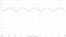
Some measurements I took that looks strange to me. Attached waveforms of output of the LTP, i.e. across drain resistor R7 (to the 2 mosfet gates). Input signal is 1 KHz sinus between +in & gnd, -in to gnd, set to give approx. 2W and 24W output power into 8 ohm resistor. Blue is signal over LTP drain resistor, red is LS output. Output THD is normal, at max 1% just before clipping. DC Bias is the standard 2 x 0.85A. Strange with such distorted signal at the mosfet gate it gives a clean output signal. Is it normal, and if it is, is it the dynamic current source who is in play?
Some measurements I took that looks strange to me. Attached waveforms of output of the LTP, i.e. across drain resistor R7 (to the 2 mosfet gates). Input signal is 1 KHz sinus between +in & gnd, -in to gnd, set to give approx. 2W and 24W output power into 8 ohm resistor. Blue is signal over LTP drain resistor, red is LS output. Output THD is normal, at max 1% just before clipping. DC Bias is the standard 2 x 0.85A. Strange with such distorted signal at the mosfet gate it gives a clean output signal. Is it normal, and if it is, is it the dynamic current source who is in play?
Attachments
Last edited:
Hi,
I made a stereo amplifier (Aleph J)that works, the adjustments are done as needed but both channels oscillate at a high frequency. I used J271 on the input and the rest is in line with the original scheme.
Someone of you still had this problem? Or do you have any suggestion as to where the problem is or what could I do?
I did not test on music, only from the generator I gave a signal. Output power is 30w. The power supply is + 0-25v from a quality laboratory source.
Thank's for any help
- Home
- Amplifiers
- Pass Labs
- Aleph J illustrated build guide