Hi, this is my first posting to this forum.
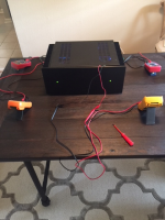
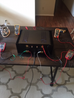
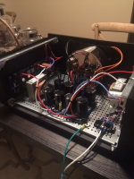
I have recently completed construction of an Aleph J amplifier. It took me many months because of the time involved in obtaining parts and bits and pieces from various overseas sources and in making decisions on the build and layout. This gave me the opportunity to read every item on this forum which proved invaluable in both providing useful information but also in averting many pitfalls.
I would like to take this opportunity to express my sincere appreciation to all involved in this site who took the initiative and effort to make available the essential components necessary to construct the amp and the follow up support and encouragement to DIYers like myself. Many thanks also of course to Mr Nelson Pass who has been so generous in making the circuit available and providing key expert advice.
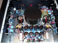
At switch on both bias and DC offset were much higher than anticipated given that I was using the recommended pot settings. However I was able to quickly correct these and after a couple of iterations reach a stable state with the correct values. Since then the amp has remained remarkably stable.
Listening to the amp has been a delight and I have been very pleased with the result.
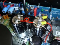
I have attached a couple of photos in case anyone is interested. Sorry for the quality.
Thank you all once again.
Peter
I have recently completed construction of an Aleph J amplifier. It took me many months because of the time involved in obtaining parts and bits and pieces from various overseas sources and in making decisions on the build and layout. This gave me the opportunity to read every item on this forum which proved invaluable in both providing useful information but also in averting many pitfalls.
I would like to take this opportunity to express my sincere appreciation to all involved in this site who took the initiative and effort to make available the essential components necessary to construct the amp and the follow up support and encouragement to DIYers like myself. Many thanks also of course to Mr Nelson Pass who has been so generous in making the circuit available and providing key expert advice.
At switch on both bias and DC offset were much higher than anticipated given that I was using the recommended pot settings. However I was able to quickly correct these and after a couple of iterations reach a stable state with the correct values. Since then the amp has remained remarkably stable.
Listening to the amp has been a delight and I have been very pleased with the result.
I have attached a couple of photos in case anyone is interested. Sorry for the quality.
Thank you all once again.
Peter
Attachments
I am building an aleph J using the DIY Audio boards....I notice on the Schematic that r8 is a 2kohm trim Pot. On the BOM, r8 is a 500 ohm trim Pot.
In the case of r7, the schematic says 2kohm trimpot and the BOM agrees.
So what should I be using for r8???
Thanks in advance...
In the case of r7, the schematic says 2kohm trimpot and the BOM agrees.
So what should I be using for r8???
Thanks in advance...
Audionut,
I used a 2k trimmer there, set at 1K. You may consider also just using
a 1K fixed resistor. See 6L6's post here:
http://www.diyaudio.com/forums/pass-labs/241729-aleph-illustrated-build-guide-203.html#post4989203
I used a 2k trimmer there, set at 1K. You may consider also just using
a 1K fixed resistor. See 6L6's post here:
http://www.diyaudio.com/forums/pass-labs/241729-aleph-illustrated-build-guide-203.html#post4989203
Thanks Dennis...
The reason I asked is because I used the BOM recommendation of 500 ohm trim pot for r8...the JFETS seem to run hot..and I am having trouble with DC Offset...can't seem to set it, and hold a setting...
I shall put in a 1k resistor and see if that helps...thanks for your reply...
The reason I asked is because I used the BOM recommendation of 500 ohm trim pot for r8...the JFETS seem to run hot..and I am having trouble with DC Offset...can't seem to set it, and hold a setting...
I shall put in a 1k resistor and see if that helps...thanks for your reply...
Hi all, would one of these toroids be suitable?
BLOCK Transformatoren-Elektronik GmbH :::: Products :::: Transformers :::: Product Details[]=5177459&v[]=4063581&v[]=5177460#
Made by Block. All 2x18v secondary, 230V primary for my region and looking at either the 300VA or 400VA version. Match the specs in the build but not sure if they are "audio" quality/suitable. Toroidy, Primrose and Antek list theirs as being suitable for audio. Last piece of the puzzle for me to purchase. Thanks
Just a general rookie question regarding the light bulb tester; what is the reasoning for it not to be used when testing bias and offset? Does it prevent the amp from sufficiently powering both boards? I could be wrong but I could have sworn you’re not supposed to use the light bulb tester when measuring bias and offset
The reason in one word is: Resistance. (Current x Resistance) volts are dropped across the bulb tester, which means the amplifier's power transformer is receiving below-normal mains voltage.
You don't want to tune up your amplifier with below-normal mains voltage, do you?
No. You want to tune up your amplifier with normal mains voltage. Which means, leave out the dim bulb tester.
You don't want to tune up your amplifier with below-normal mains voltage, do you?
No. You want to tune up your amplifier with normal mains voltage. Which means, leave out the dim bulb tester.
The reason in one word is: Resistance. (Current x Resistance) volts are dropped across the bulb tester, which means the amplifier's power transformer is receiving below-normal mains voltage.
You don't want to tune up your amplifier with below-normal mains voltage, do you?
No. You want to tune up your amplifier with normal mains voltage. Which means, leave out the dim bulb tester.
Ah ok. Thanks for the insight!
What Mark said is completely correct.
The Bulb Tester is a crude but effective tool to keep really bad things from happening if there is a short or some error to make the circuit pull a ton of current. Because the bulb is wired in series with the load, it will glow when a bunch of current is drawn past it, and because it's a resistor, the voltage will be lower on the far end (where the amp is) the lower voltage hopefully keeping things from burning up.
Now the Aleph J is self-biasing to a certain extent, and the pot we use as 'bias' really isn't - it's the AC current gain of the constant current source. But it effects the current flow through the output stage and so it's sorta biasy. So let's consider it bias.
Anyway, because the circuit is setup to bias up by itself and sit there in glorious single-ended Class-A, there is always A LOT of current flowing when the amp is turned on. Which will glow the lamp, which will drop voltage across the bulb and into the amp, which will make it turn on less.
Now, imagine setting the bias pot to read correctly with the Bulb Tester connected - the bias reads low, because the line voltage is being starved, so you turn it up, which makes the bulb glow a bit more, so you turn the bias up even more, and you are fighting a negative feedback loop.
SO, now you have the bias turned up to 11, the bias now is reading in the general ballpark, although low, but everything else seems to be behaving sorta kinda properly, so you unhook the bulb tester and decide to plug it in bare and see what happens.
But remember, the bias is turned up all the way since previously you were fighting the voltage drop of the bulb, and now, with the full AC mains available, it pulls a TON of current since you set the bias pot there, possibly burning things up.
To sum up; The Bulb tester is to catch gross errors. It does this crudely but effectively. If the amp is working properly the bulb tester inhibits proper operation.
What Mark said is completely correct.
The Bulb Tester is a crude but effective tool to keep really bad things from happening if there is a short or some error to make the circuit pull a ton of current. Because the bulb is wired in series with the load, it will glow when a bunch of current is drawn past it, and because it's a resistor, the voltage will be lower on the far end (where the amp is) the lower voltage hopefully keeping things from burning up.
Now the Aleph J is self-biasing to a certain extent, and the pot we use as 'bias' really isn't - it's the AC current gain of the constant current source. But it effects the current flow through the output stage and so it's sorta biasy. So let's consider it bias.
Anyway, because the circuit is setup to bias up by itself and sit there in glorious single-ended Class-A, there is always A LOT of current flowing when the amp is turned on. Which will glow the lamp, which will drop voltage across the bulb and into the amp, which will make it turn on less.
Now, imagine setting the bias pot to read correctly with the Bulb Tester connected - the bias reads low, because the line voltage is being starved, so you turn it up, which makes the bulb glow a bit more, so you turn the bias up even more, and you are fighting a negative feedback loop.
SO, now you have the bias turned up to 11, the bias now is reading in the general ballpark, although low, but everything else seems to be behaving sorta kinda properly, so you unhook the bulb tester and decide to plug it in bare and see what happens.
But remember, the bias is turned up all the way since previously you were fighting the voltage drop of the bulb, and now, with the full AC mains available, it pulls a TON of current since you set the bias pot there, possibly burning things up.
To sum up; The Bulb tester is to catch gross errors. It does this crudely but effectively. If the amp is working properly the bulb tester inhibits proper operation.
Ok that makes perfect sense. Thank you for the detailed explanation!
A while back, I ordered the ALEPH J TRANSISTOR KIT from the store. I forgot that the kit included 6 transistors with the Mosfets and I installed the Zetex ZTX550 and 450s I ordered from Mouser.
Is there any reason I should switch them out for the ones from the DIY store? They don't need to match, do they?
Is there any reason I should switch them out for the ones from the DIY store? They don't need to match, do they?
Hi all,
First-of all thanks to all who put in here their know-how and experience !
DIY audio is my favourite forum although sometimes hard to follow as English is not my first language.....
I’m attempting to jump on the DIY built of Pass Aleph J (missed the preorder of the aca kit)
Is the BOM on the first page “up to date”?!
Because I find more and more changes whlie reading the built thread!
Like R8 is recommended to be fixex 1kR....
Gregor
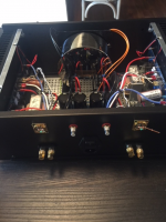
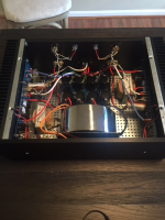
Big thanks for 6L6 for answering my endless questions as this was my 1st amp build and Papa for sharing his work I was finally able to give birth to a 40lb bouncing baby Aleph J. A few complications in the 3rd trimester but all came out great. Just a few tidbits; I used a transformer from Toroidy and CLC filtering for the power supply. The binding posts, XLRs and chassis RCAs are from Cardas. I was also able to source some Toshiba Jfets as well. For C1 I decided not to use the Wima (I’ve heard them before and didn’t like them, just preference) and instead had Jens Nielsen of Ophelia Caps custom make the film caps for me. Jens spaced out/strengthened the leads to fit the boards and also fortified the casing to withstand the internal heat. Just like the Humble Homemade review the caps really don’t add much to the sound, being a tad warmer from neutral. I tried them w the Elnas and wasn’t my cup of tea (maybe I didn’t let them burn in enough) being congested in the mids but after changing the Elnas w/ Nichicons, everything smoothed out and opened up. I think the Ophelia’s like other parts that are on the neutral side hence why the Humble reviewer had slight congestion, either way I really like this cap as I got no congestion after the change and will use it on other builds if a film cap is needed.
I’ve never heard a First Watt amp so was going on forum members reviews and I must say this is an awesome amp! Very laid back w/ good sound staging and mellow highs. Completely different from the previous bridged Classe CA-100s I was using which were on the darker side in the mids. I look forward to building more of these as the Aleph J needs some siblings!
I’ve never heard a First Watt amp so was going on forum members reviews and I must say this is an awesome amp! Very laid back w/ good sound staging and mellow highs. Completely different from the previous bridged Classe CA-100s I was using which were on the darker side in the mids. I look forward to building more of these as the Aleph J needs some siblings!
Attachments
Last edited:
well , you even didn't need that cap
")
Yea I'm not up to your level of expertise. I'm following that build guide to the T haha. I got a lot to learn. Also thanks for the help as well, its greatly appreciated
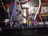
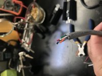
Balanced and RCA input wiring
Getting near the end of my Aleph J project, it’s my first amplifier and has been a great learning experience, thanks everyone for all of your posts! Question on wiring both balanced and rca inputs in single chassis. I have some 6 conductor wire that is shielded and sports an uninsulated ground wire. I was going to run one wire each from +v rca and xlr terminating each to +v input on board, same with -v . Now I’m not sure if I should use the bare shield wire connected to the ground on the xlr and terminate on the chassis or use one of the other insulated wires in the package. From my reading here grounding is very important with respect to noise elimination, perhaps I should keep it simple and just use some standard wire. Does anyone see an advantage to the insulated cable?
Getting near the end of my Aleph J project, it’s my first amplifier and has been a great learning experience, thanks everyone for all of your posts! Question on wiring both balanced and rca inputs in single chassis. I have some 6 conductor wire that is shielded and sports an uninsulated ground wire. I was going to run one wire each from +v rca and xlr terminating each to +v input on board, same with -v . Now I’m not sure if I should use the bare shield wire connected to the ground on the xlr and terminate on the chassis or use one of the other insulated wires in the package. From my reading here grounding is very important with respect to noise elimination, perhaps I should keep it simple and just use some standard wire. Does anyone see an advantage to the insulated cable?
Attachments
Last edited:
- Home
- Amplifiers
- Pass Labs
- Aleph J illustrated build guide