If you are using a single-ended input (RCA) the pin needs to be attached to "+ IN", the outer connection to GND, and "- IN" jumpered to GND.
It shouldn't hum at all, you have something mis-wired...
Glad you mentioned this. Just getting ready to wire mine up, and looking at your build guide, I was wondering what that little wire looping over to ground was! If one would like to wire it balanced, other that having appropriate input jack, is there a diagram showing proper wiring? I see one pick in the build guide where someone did this, (Grimberg) but I cant follow the wires with any certainty....
Thanks for any guidance dumbed down enough for me to follow...
Russellc
Last edited:
A few Google images for XLR wiring
https://www.google.co.uk/search?q=x...A%2F%2Fwww.scotaudio.com%2Fwiring.htm;400;194
Don't forget the link between pins 1 & 3 when using RCA input.
https://www.google.co.uk/search?q=x...A%2F%2Fwww.scotaudio.com%2Fwiring.htm;400;194
Don't forget the link between pins 1 & 3 when using RCA input.
Yes, I want to do it like the pic in the 6L6 guide, with both rca and xlr. I'll work up a drawing of how I think you guys are explaining so you can give it a look if I have it right. The way Grimberg did it is how I want to do it. I saw no switching, just the RCAs and the XLRs. I just cant tell whats hooked up to what on the XLRs in the pic.
Thanks again guys!
Russellc
Thanks again guys!
Russellc
Last edited:
Is this how Grimbergs is in the pic? It looks like there is a green jumper going from the center of the RCA to the right side of the XLR, the ground connection?(looking at the diagram provided by Mara, "post 1")
Then it looks like another green wire attached to the same connection on the XLR as the green jumper, and that goes back to the pcb to the Ground? (That doesnt seem right, but I have no idea) Your response says RCA inside to V+, (which makes more sense) I must be missing something on that.
Then there is a red wire going to xlr pin on the left side, diagram shows as "+" (pin 2 in Mara diagram) and then goes back to pcb +in?
That leaves the black wire, which appears to go to the lower pin on xlr "-" (pin 3 on Mara diagram) and I assume goes to the -in on pcb? It also appears (black wire) to jumper over to the outside of RCA.
Your instructions are clear, I'm just having trouble charting them out on Grimbergs pic.
Finally by "Dont forget the jumper in xlr when using rca" is that the small jumper shown that I commented on in 1161, or have I missed something else?
I appreciate your bearing with me!
Russellc
Russellc,
You can see a slightly larger version of the pictures in the original posting.
http://www.diyaudio.com/forums/pass-labs/224881-aleph-j-universal-mounting-spec-13.html#post3481260
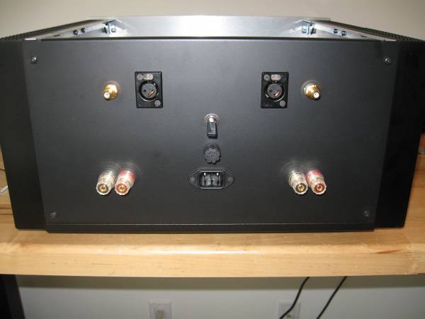
As Jim (6L6) correctly described, I first made the connection between the XLR jack and the board. On the back of the XLR the pins are numbered this way:
1 - Ground
2 - Positive
3 - Negative
Go to this page and click on the "Drawing NC3FD-L-1" link to see a pdf file of how the pins are numbered. It may help you understand the picture.
After connecting the XLR to the board, I connected the RCA jack to the XLR jack. Only the Positive and Ground are connected.
When using the XLR, leave the RCA disconnected. When using the RCA, short pins 1 and 3 of the XLR. I made a U-shape bridge using 18 AWG gauge wire.
I hope this helps.
You can see a slightly larger version of the pictures in the original posting.
http://www.diyaudio.com/forums/pass-labs/224881-aleph-j-universal-mounting-spec-13.html#post3481260
As Jim (6L6) correctly described, I first made the connection between the XLR jack and the board. On the back of the XLR the pins are numbered this way:
1 - Ground
2 - Positive
3 - Negative
Go to this page and click on the "Drawing NC3FD-L-1" link to see a pdf file of how the pins are numbered. It may help you understand the picture.
After connecting the XLR to the board, I connected the RCA jack to the XLR jack. Only the Positive and Ground are connected.
When using the XLR, leave the RCA disconnected. When using the RCA, short pins 1 and 3 of the XLR. I made a U-shape bridge using 18 AWG gauge wire.
I hope this helps.
![IMG_3992[1].JPG](/community/data/attachments/426/426442-94e2d9d67cf70919cddb9095ecc2a157.jpg)
Russellc,
You can see a slightly larger version of the pictures in the original posting.
http://www.diyaudio.com/forums/pass-labs/224881-aleph-j-universal-mounting-spec-13.html#post3481260
As Jim (6L6) correctly described, I first made the connection between the XLR jack and the board. On the back of the XLR the pins are numbered this way:
1 - Ground
2 - Positive
3 - Negative
Go to this page and click on the "Drawing NC3FD-L-1" link to see a pdf file of how the pins are numbered. It may help you understand the picture.
After connecting the XLR to the board, I connected the RCA jack to the XLR jack. Only the Positive and Ground are connected.
When using the XLR, leave the RCA disconnected. When using the RCA, short pins 1 and 3 of the XLR. I made a U-shape bridge using 18 AWG gauge wire.
I hope this helps.
Thanks, I think I've got it, and thanks for the additional info! Nice build, and I have wondered about wiring the thermisitors correctly when 2 transformers are used. Are the jumpers I see on your XLR plugs in place of the small ones 6L6 used on the boards of his non XLR example?
PS, yes I see that they are now, thanks for the link!
Russellc
Last edited:
Now do I have it right?
In your diagram, the RCA is connected to pins 2 and 3 on the XLR jack. It should be pins 1 and 2. Pin 3 of the XLR is not connected to the RCA. The wire bridge is used to make the pin 3 connection to ground when the RCA is in use.
In your diagram, the RCA is connected to pins 2 and 3 on the XLR jack. It should be pins 1 and 2. Pin 3 of the XLR is not connected to the RCA. The wire bridge is used to make the pin 3 connection to ground when the RCA is in use.
I was just noticing 6L6 comment above that the "outside of the RCA goes to Gnd"....Thanks! I think one thing that was confusing me is that I couldnt see the black wire under the red one on the xlr, and just assumed it went to the lower negative one...
Russellc
Last edited:
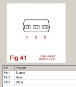
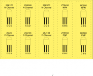
I feel like an idiot for this not being readily apparent to me, but looking at the datasheet for the 2SJ108 it isn't all that clear which pin is which.
I suppose the easiest way to ask this is, do the sides of the 2SJ108 with writing on them (the longer flat side) face towards or away from each other when placed in Q1A and Q1B?
(This would be easier if there was only 1 flat side!)
I suppose the easiest way to ask this is, do the sides of the 2SJ108 with writing on them (the longer flat side) face towards or away from each other when placed in Q1A and Q1B?
(This would be easier if there was only 1 flat side!)
I feel like an idiot for this not being readily apparent to me, but looking at the datasheet for the 2SJ108 it isn't all that clear which pin is which.
I suppose the easiest way to ask this is, do the sides of the 2SJ108 with writing on them (the longer flat side) face towards or away from each other when placed in Q1A and Q1B?
(This would be easier if there was only 1 flat side!)
This may be help you ...
Attachments
ZM you are an absolute champion. Thanks!
Lucky for me, it is the exact opposite of where I was leaning too. Never been so glad to ask a stupid question in my life
I've had the same issue before...took me awhile to realize some of these pics are like a X-ray view from above, not looking up at the pins. You really don't want to fry those rare fets! BTW, post 1175 is a bottom view...
Last edited:
- Home
- Amplifiers
- Pass Labs
- Aleph J illustrated build guide