Any idea why and how to fix this?
It's around 1% differance, most likely the feedback resister tollerance, either use matched resistors or tweek one of the values.
made by which schematic exactly ?
Schematic attached. I used boards for diyAudio Strore. Some photos here: Aleph J
Attachments
It's around 1% differance, most likely the feedback resister tollerance, either use matched resistors or tweek one of the values.
You mean R4 (221k) on the schematic attached above, am I right?

Transformer?
Since I concider to build this amplifier but have still to buy the PCB:s and transfomer amongst other then the question arise:
Original is 2x18V and about 300 VA, now we learn that it is possible to run the amp on 2x27V...
Since I still have to order a tranformer the question is if I should go for 2x18V as intended in the shematics or should I order 2x22V for example?
Seem that 2x22V or 2x24V should be doable without any other changes to the schematics and with a even better result.
To do or not to do, that is the question!
Is Aleph gain set by R4/R1 (221k/22.1k)?
First of all, are you running the amplifier in balanced mode or single ended?
If balanced, R4 must equal R2 and R3 must equal R1.
If you are running single ended (-IN connected to 0V), the above is not so important.
The gain should be x10 (+20dB) and is determined by R4/R3, C1 will reduce the gain at low frequancys -3dB @ 7.2Hz.
It would be best to make gain measurements well away from the cutoff frequancy, somewhere around 1KHz.
Last edited:
First of all, are you running the amplifier in balanced mode or single ended?
If balanced, R4 must equal R2 and R3 must equal R1.
If you are running single ended (-IN connected to 0V), the above is not so important.
The gain should be x10 (+20dB) and is determined by R4/R3, C1 will reduce the gain at low frequancys -3dB @ 7.2Hz.
It would be best to make gain measurements well away from the cutoff frequancy, somewhere around 1KHz.
Thanks for the explanation, it is very helpful. Actually I run Aleph in both modes - balanced in my digital setup and single ended when connected to Pearl 2.
I measured gain in single ended mode, -IN connected to GND, at 1kHz. I also measured and compared values of R1 - R4 in both channels and they are quite different, but within 1%. I will probably try to match them, or replace them with 0.1% resistors...
More questions
More funny thoughts!
I have 10 x 15000uF 63V but I also found some six pieces of 4700uF 63V so if I now whant to go from 150 000uF to 172 000uF where do I preferably put the small ones?
Logic is saying that small is faster so in the end of the PSU to have fast response from the PSU but there is maybe other things to concider that I am missing.
Just completed Aleph J lights up for a little while, then two blown fuses
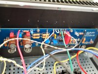
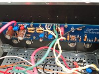
So I switched on my new baby and was very happy to see all the LED's light up as they should. Then I switched it off, while I put the bottom bracket on and did a couple other things. When I turned it back on, no lights and two blown fuses. I used 250 V, 2 amp fast blo. Here are some pics, I haven't tidied up the wiring yet. Any ideas?
So I switched on my new baby and was very happy to see all the LED's light up as they should. Then I switched it off, while I put the bottom bracket on and did a couple other things. When I turned it back on, no lights and two blown fuses. I used 250 V, 2 amp fast blo. Here are some pics, I haven't tidied up the wiring yet. Any ideas?
Attachments
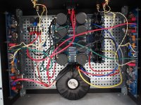
What criteria did you use to choose a 2A valued fuse? Did you use a slow blow type?
What is the VA rating of your transformer? Typically the fuse for the primary should be VA divided by 120V, then multiply that result by 125-150% (due to a turn on surge).
Yes, please twist all primary and secondary windings from your transformer.
Best,
Anand.
What is the VA rating of your transformer? Typically the fuse for the primary should be VA divided by 120V, then multiply that result by 125-150% (due to a turn on surge).
Yes, please twist all primary and secondary windings from your transformer.
Best,
Anand.
I always use a 3 amp slow blow in all my amp builds, tube or SS. If there is a dead short somewhere it will blow just as quick as the 2 amp. Hopefully for you the normal turn on surge blew the 2 amp fuse.
qwertyl's comment about the RCA connection is correct, a common mistake on the J build I made myself and a friend of mine who just built did as well. Without being connected correctly you are subject to hum and most definitely low gain.
qwertyl's comment about the RCA connection is correct, a common mistake on the J build I made myself and a friend of mine who just built did as well. Without being connected correctly you are subject to hum and most definitely low gain.
Ok, so I followed your advice, and first the good, everything lights up again, and no blown fuses. Now, the bad, while I can zero out the offset and set the bias ok on the left channel (looking at the front of the amp), on the right I get an offset reading of negative 21.65 volts, and no amount of turning on R7 changes this. I checked everything and I don't have any wires reversed. What gives?
Larry
Larry

Pass DIY Addict
Joined 2000
Paid Member
I would echo those who have said to use slow-blow fuses to survive the power inrush at turn on. 2-3A should be plenty. As for rail voltage on your speaker output, I would check the mounting of your output mosfets. If you used a silpad and tapped your own holes in the sinks, check for a bur or sliver of aluminum from the sink that may be piercing the pad and grounding the mosfet to the sink.Any ideas?
- Home
- Amplifiers
- Pass Labs
- Aleph J illustrated build guide