I would say that I do consider current flows, grounding issues, location of star ground, loop areas, component placement with respect to EMI, etc., in my builds.
I am happy to hear no noise from my 103dB speakers with my ears against them. And yes, the power is turned on and the amplifier is connected to the speakers.")
I am happy to hear no noise from my 103dB speakers with my ears against them. And yes, the power is turned on and the amplifier is connected to the speakers.
I've routed my speaker returns to the power supply ground (along a minimum loop area path) as well as just back to the output stage and I've had success with both methods.
My last amp build, the LD1014D follower, I used a circuit board for the output stage and returned the speaker ground to the ground terminal of the decoupling capacitor on the PCB. My test measurements at 1 watt output do not show excessive noise.
My last amp build, the LD1014D follower, I used a circuit board for the output stage and returned the speaker ground to the ground terminal of the decoupling capacitor on the PCB. My test measurements at 1 watt output do not show excessive noise.
Attachments
Jan Didden, a highly respected audio electronics professional, has recommended that speaker ground be connected to amplifier ground:
https://www.diyaudio.com/community/...no-blocks-in-same-chassis.410606/post-7634666
https://www.diyaudio.com/community/...no-blocks-in-same-chassis.410606/post-7634666
For the power amp PCBs I've laid out and put in the Store, I like to provide a speaker-ground connection point right next to the speaker-hot connection point. (usually: 6.35mm FastOn blades). Then the builder can run a tightly twisted pair of wires from amp PCB to speaker binding posts. If for some reason they don't like what they hear, they can always move the speaker-cold wire to a ground on the PSU PCB, and decide whether they like that arrangement better.
I've kept increasing the Aleph J bias over time. Am at 490 (cold) - 460 (warm) at the moment. It sounds really good... it simply shows what the source (and interconnects) are capable of. Maybe consider 5U chassis..? You won't regret it. It does look like an elephant in the room, though.
hi extreme_boky,I've kept increasing the Aleph J bias over time. Am at 490 (cold) - 460 (warm) at the moment. It sounds really good... it simply shows what the source (and interconnects) are capable of. Maybe consider 5U chassis..? You won't regret it. It does look like an elephant in the room, though.
I found an earlier post you made regarding the bias where you felt it was better at around 430mV. did something change in your amp, or did you just decide to try it again at a higher bias? I have mine right around 450mV and seems it is the "sweet spot". I did try it higher, around 470mV, but something wasn't right with the sound.
hi extreme_boky,
I found an earlier post you made regarding the bias where you felt it was better at around 430mV. did something change in your amp, or did you just decide to try it again at a higher bias? I have mine right around 450mV and seems it is the "sweet spot". I did try it higher, around 470mV, but something wasn't right with the sound.
I found the more I paid attention to my source and, in particular, its power supply, the more I craved higher Aleph J bias.
But the real quantum leap in Aleph J sound quality that simply demanded a high bias setting, was when I realised that the DC offset pot acts as an I/V... it was right there in front of my eyes.. ah well... I can not believe (and can't forgive myself) I didn't see it. Once I replaced the trim pot with a discrete resistor... well, what can I say... the history was written right there and then. I started with AB carbon resistor but settled (very quickly) on the TX2575 Naked Foil Resistor, which incidentally gave superior results with my DIY DACs of the previous era.
I think the trim pot replacement with a discrete resistor type of a "DAC I/V quality", is simply a must; it is the best thing one could do in an Alep J.
The only limiting factor is to ensure the rest of the system is up to the task because Aleph J's revealing capabilities would approach brutality.
Or, look at it from a different angle... "oh shi&... I think I should do something about my source now (and interconnects, speakers)."
That's what Aleph J does to a system.
Last edited:
That's great, thanks for the detailed answer. I'm familiar with the resistors you mentioned, I used them in my TDA1541A DAC project.
With regard to the bias pot R27 - my only concern about using a fixed resistor is that, would the bias continue to change over time as components run in? How long have you had the fixed in place, and has there been any appreciable change?
Looks like there's no way of escaping the fact the board has to come out along with the power devices!
Yeah... have a few Keratherm spare sets handy.
The DC offset in my case varies a bit.. but I do not have C1s, i.e. the C1s are bypassed with a copper link.
The most important thing is to find the R7 (you said R27... that's the bias trim-pot) resistance value when the DC offset settles between + and - 10mV for the given temperature that you'll have present in your room most of the time, with the lid closed. Once happy with the DC offset variations, measure the R7 trim pot resistance for each channel. Then ask Texas Components to make the required resistors for you.
The change in DC offset will come with a change in room temperature. You'll need to play with bias and offset a bit, have 4 multimeters connected at all times, the lid closed, let the amp warm up for at least an hour... and then adjust the trim pots (quickly... while the lid is removed). Then close (wait 10-15 minutes), and re-check.
With C1 still in use, you should be able to get to + and -10mV DC offest range with no problem at all...
Note that with a typical speaker sensitivity of about 86dB/W @ a metre distance, you won't worry (at all) if the DC offset varies between + and - 50mV... I'd go as high as + and -70mV.
At around + and -80mV, I can hear faint plops/clicks (but only just if the room is completely quiet), if I engage the mute relays (short XLR - and + to ground) in May DAC. This is from a 4.5 meter speaker distance to the listening position.
Last edited:
I am convinced that the mains power on/off plops have reduced in intensity as well... and I have a theory here. The reduced capacitance, as the result of the removed trim-pot, helps the current (thru Q1A) reach the return path (negative rail) quicker (during power OFF transition) - therefore shutting the +4V voltage difference at the amplifying MOSFETs (Q7 and Q8) quicker.
Same reason why the sound is so much better without the trim-pot - less capacitance for JFETs to drive (in parallel with whopping MOSFETs capacitance they have to drive). Not to mention the scrubbing/rubbing wiper to substrate contact resistance... that gets completely removed from the signal path.
Same reason why the sound is so much better without the trim-pot - less capacitance for JFETs to drive (in parallel with whopping MOSFETs capacitance they have to drive). Not to mention the scrubbing/rubbing wiper to substrate contact resistance... that gets completely removed from the signal path.
For experimenters…Consider a 3 pin header, like this if desoldering pots makes you nervous. Or use Rainfall Sky’s Aleph J SS board where he allows for replacement of pot with a stand alone resistor. See the Aleph J SS thread. Thanks to Extreme_Boky for his subjective experiments.
Best,
Anand.
Best,
Anand.
Okay, got it now. You are saying to replace the DC offset pot with a fixed resistor. I was thinking bias pot...heheYeah... have a few Keratherm spare sets handy.
The DC offset in my case varies a bit.. but I do not have C1s, i.e. the C1s are bypassed with a copper link.
The most important thing is to find the R7 (you said R27... that's the bias trim-pot) resistance value when the DC offset settles between + and - 10mV for the given temperature that you'll have present in your room most of the time, with the lid closed. Once happy with the DC offset variations, measure the R7 trim pot resistance for each channel. Then ask Texas Components to make the required resistors for you.
The change in DC offset will come with a change in room temperature. You'll need to play with bias and offset a bit, have 4 multimeters connected at all times, the lid closed, let the amp warm up for at least an hour... and then adjust the trim pots (quickly... while the lid is removed). Then close (wait 10-15 minutes), and re-check.
With C1 still in use, you should be able to get to + and -10mV DC offest range with no problem at all...
Note that with a typical speaker sensitivity of about 86dB/W @ a metre distance, you won't worry (at all) if the DC offset varies between + and - 50mV... I'd go as high as + and -70mV.
At around + and -80mV, I can hear faint plops/clicks (but only just if the room is completely quiet), if I engage the mute relays (short XLR - and + to ground) in May DAC. This is from a 4.5 meter speaker distance to the listening position.
So you are not using the DC coupling cap...what do you about it before the offset drops to a reasonable level? Not engage the mute relay until it does?
Yes. Too bad the original board didn't take advantage of a simple shunting header and one empty resistor spot above R7and that would have negated removing the board and pot.For experimenters…Consider a 3 pin header, l
Sorry if this question has been asked. I did a simple search but couldn't find anything. Has anyone tried (or not for some reason) to parallel another set of drivers? It seems like a reasonable thing given the circuit topology? Add another pair to the right of Q6,Q8 with source resistors and modify/change R20-23.
Your set up is a bit more evolved than mine, and of course we each have our own preferences, speakers, other gear etc.I've kept increasing the Aleph J bias over time. Am at 490 (cold) - 460 (warm) at the moment. It sounds really good... it simply shows what the source (and interconnects) are capable of. Maybe consider 5U chassis..? You won't regret it. It does look like an elephant in the room, though.
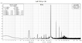
With that said, with a slightly different Aleph J, my ears and measurements match your experience. I have a variant running at ~2A bias current per channel, which is roughly the same as your "460 (warm)"
With every Aleph variant I've tested (several iterations of the J, and an A60 variant) the THD reduces with increased bias. Some iterations and variants more so than others. The A60 trends the same way, but my measurements (and ears) don't detect quite as much difference. I have no idea why, but it's fun.
Thanks as always for sharing your experiences. They're always on my list for things to try and learn. I've had swapping out my offset pot with a fixed resistor on my list for a while now in one of my builds. I may have to get off my rump and give it a go... even if I haven't the foggiest of clues why it acting like an I/V matters.

--------------
'Typical' AJ built with the boards offered in the store and with 'standard' parts. This was done rather quickly, I'm not sure that 4R trend beyond the knee would hold at the highest bias, but... ?

Another AJ variant. Same rough trend.

A60

Note - Should folks take any data I post as gospel, NO. Still learning. Posted for entertainment only.
- Home
- Amplifiers
- Pass Labs
- Aleph J illustrated build guide