Anyone?Oh, one question. If R6 and R30 are jumpered, and in the LTP bias position is a 2K pot, where to measure to ensure the pot is set to 1K (as I forgot setting this in the procedure)? What should be the voltage at the top (emitter ) of Q2 or below R8 with respect to ground?
Thanks!
Thanks!
I hope I'm looking at the right location, but I suspect trying to confirm R8 is at 1K by looking at the voltage where Q2 and R8 meet will be tricky.
The voltage there is basically the V+ voltage minus the voltage across R8. But by design the voltage across R8 nominally is approx 9.1 - 0.7 over a fairly wide current range across R8 (and R8 value).
Hopefully others can chime in.
The voltage there is basically the V+ voltage minus the voltage across R8. But by design the voltage across R8 nominally is approx 9.1 - 0.7 over a fairly wide current range across R8 (and R8 value).
Hopefully others can chime in.
That's what I did before initial power up.
In some of the old post, when R6 is 562 ohms, LTP bias pot is adjusted so that the voltage across R6 is about 4.7 volts if I recall correctly.
Because of my paranoia, I am contemplating on ripping the pot and changing it to a fix 1k resistor")
In the good news department, I have no problem setting the bias (I tried up to 500 mV) and currently set at 450 mV and stable +/- 1-2 mV, and offset (sitting at 0.13 and 0.6 L&R channel respectively). Best of all it sounds good! Here it is driven by a BA-3 making emotions!
Thank you both Dennis and Kevin!

In some of the old post, when R6 is 562 ohms, LTP bias pot is adjusted so that the voltage across R6 is about 4.7 volts if I recall correctly.
Because of my paranoia, I am contemplating on ripping the pot and changing it to a fix 1k resistor
In the good news department, I have no problem setting the bias (I tried up to 500 mV) and currently set at 450 mV and stable +/- 1-2 mV, and offset (sitting at 0.13 and 0.6 L&R channel respectively). Best of all it sounds good! Here it is driven by a BA-3 making emotions!
Thank you both Dennis and Kevin!
Last edited:
You sure that’s not 33,5mV and 57,99?R16 and R17 (upper half) = 34mV
R18 and R19 (lower half) = 56mV
With risk of sounding like a complete dork: could Amandarae not just follow Mighty’s advice and measure the AC voltage drops across output the output stage source resistors, and adjust R7 and R8 pots to suit? Of course, it wil help if the lower half is set to spec first.
Alternatively, use a distortion analyzer and scope to adjust the residual to spec phase and amount of distortion?
Haha, probably easier to put in a fixed resistor
Alternatively, use a distortion analyzer and scope to adjust the residual to spec phase and amount of distortion?
Haha, probably easier to put in a fixed resistor

Yes, I'm sure that when measuring with one particular meter at ~1W I get 34mV (upper half) and 56mV (lower half). Measuring with a different meter (know to be more accurate) at ~1W the reading is 32.75mV and 55.49. So 34 being 59% of 56 and 32.75 being 60% of 55.49, wouldn't either of these measurements be accurate enough for our purpose here?You sure that’s not 33,5mV and 57,99?
Edit:
This testing is in preparation for connecting this amp to a friends Altec 604e which present a 16 ohm load.
Last edited:
The J was made to tackle those loads. ZM is the test leader so he needs to verify your measurements. But it might prove fruitful to first measure presenting an 8R load, then trying 16, to see how the Aleph CCS corresponds to the two.Yes, I'm sure that when measuring with one particular meter at ~1W I get 34mV (upper half) and 56mV (lower half). Measuring with a different meter (know to be more accurate) at ~1W the reading is 32.75mV and 55.49. So 34 being 59% of 56 and 32.75 being 60% of 55.49, wouldn't either of these measurements be accurate enough for our purpose here?
Edit:
This testing is in preparation for connecting this amp to a friends Altec 604e which present a 16 ohm load.
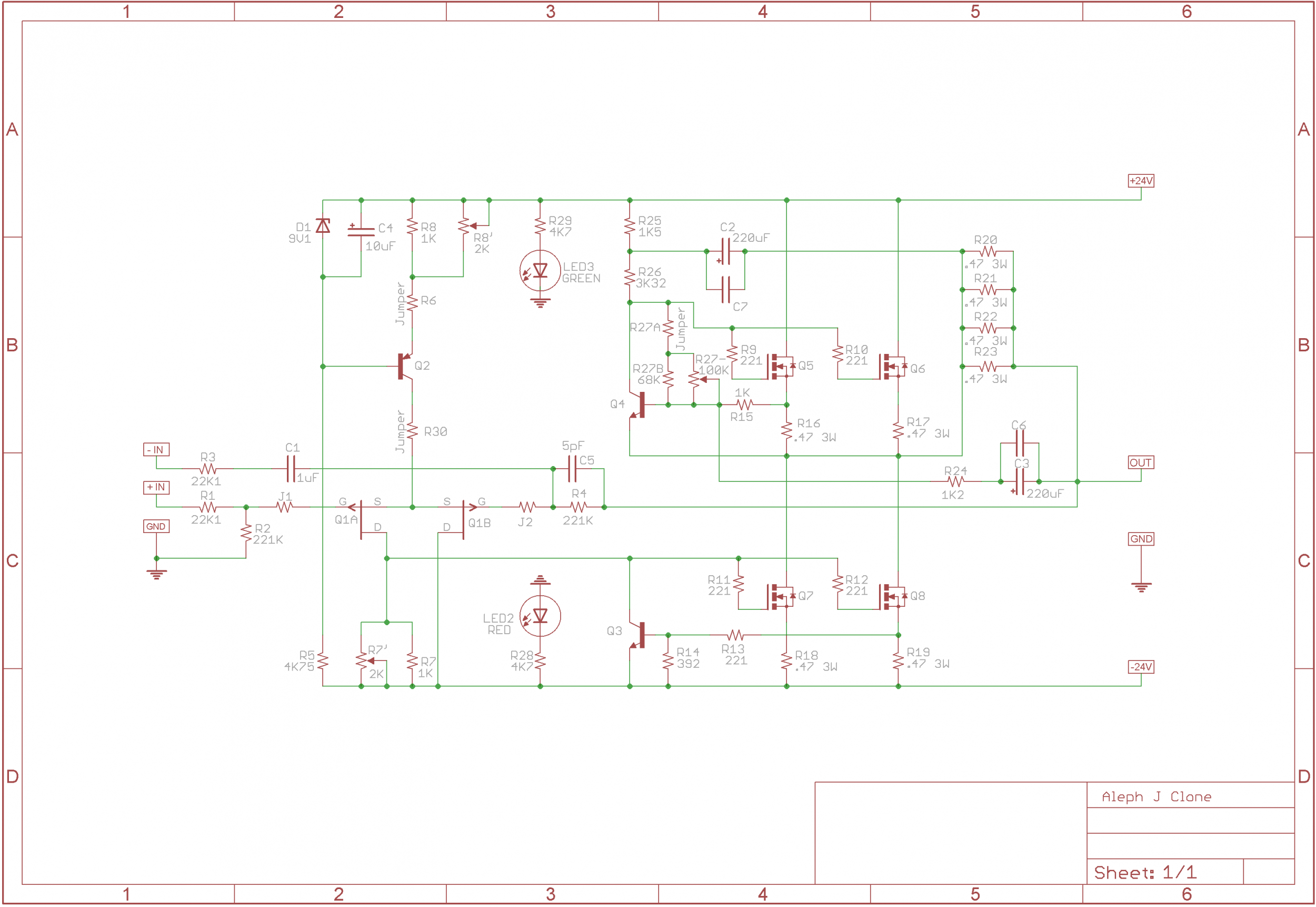
This is the exact Aleph J Schematic I'm using. It's in post #1 of this thread. I used PCBs from the diyAudio Store and completed using Jim's Build Guide.
Measuring with a 16ohms load produces 17.9mV upper half, 30.6mV lower half, having about the same ratio of 59% as the 8ohm load.But it might prove fruitful to first measure presenting an 8R load, then trying 16, to see how the Aleph CCS corresponds to the two.
After several days of using the amp, the sound of the amp is fine! If I can only minimize the turn-Off thump (extends my Fostex 94 dB driver to about an estimate of 1/4 inch or greater (also with my 99dB driver which I believe extends further and louder) excursion and definitely audible. I have the soft start from Mr. Mark J (H9KPXG) and no worries about turning the amp On.
- Home
- Amplifiers
- Pass Labs
- Aleph J illustrated build guide