JFETs have sort of a capacitive barrier between the gate and the source and/or drain.
JFETs have a reverse-biased PN junction between the gate and the source/drain. The J in their name stands for Junction.
You are thinking of a MOSFET which has an insulator (silicon dioxide) between the gate and the source/drain. MOS stands for Metal Oxide Silicon.
I am confuse. How do I connect xlr inputs + - groundIt has balanced input; no need to add anything.
sorry for the naive q
Eitan100,I am confuse. How do I connect xlr inputs + - ground
sorry for the naive q
Take a look at the A75 schematic page 11 on the: art_a75_2.pdf
It's crystal clear!
Attachments
I am confuse. How do I connect xlr inputs + - ground
sorry for the naive q
Last edited:
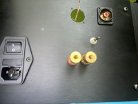
Thank you. I guess if I want to install both xlr and rca sockets I need to bridge minus and ground pins on the xlr when I am using unbalanced?
Timely discussion. I'm in the final stages of doing exactly this. I took a 3PDT ON-ON switch (this) and simply joined negative and ground at the RCA input. Then did some ham-fisted hole drilling.I guess if I want to install both xlr and rca sockets
Attachments

Still having problems same channel. I replaced all transistors with matched ones. It worked fine for a while but then back to same issue , 15 volts on output , current through output mosfets is fine, some oscillation at 120 hz, no effect R7. R19 gets very hot, but no other component does.
The above doesn't make sense. The reason R19 gets hot is a very high current running through Q8."Current through output mosfets is fine" vs. "R19 gets very hot, but no other component does".
What does the above mean? How did you measure the oscillations and where? With or without the load attached?some oscillation at 120 hz, no effect R7.
"No effect R7"...? Does this mean that turning the R7 trim-pot does not do anything? Did you check the trim-pot? Is it soldered correctly? Shows us in the photo...
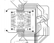
Provide the following:
1. The top-view photo of your amplifier - showing wiring, high-res, and well-lit.
2. The photo of your faulty AMP PCB - top and bottom, high res and well-lit.
3. Enter the measured voltage levels per the attached photo - see the (seven) arrows. No load attached.
Last edited:
Thank you very much for your reply and interest. The answers to questions are as follows:
1. Perhaps not so much oscillation now as leakage of power supply voltage. See scope photo of output, works out to approx. 166 Hz by my calculation. No load, shorted input. DC offset at start up is 15-16 volts and does not go away. The pot at R7 has little effect.
2. R19 still gets hot.
3. R27 does work and adjusts the bias current.
4. Measured voltages: across R16 - 368 mv, across R17 - 370 mv, across R18 - 250 mv, across R19 - 472 mv.
5. voltage across D1 - 9.15 v; across R7 pot - 4.4v., Q4 collector to emitter - 660mv.
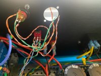
I figured out at least partly what I think happened. The input jack is connected to shielded cable, the wire shield being the negative ground for the input. Unnoticed,it came loose, so the input was not shorted out or terminated in some way. I saw wild high frequency oscillation on the scope connected to the speaker terminals before discovering the fault. Since then, what I get looks sort of like a triangle wave, at what appears to be a multiple of the 60Hz line frequency. Re. photos:
sorry about the angle of view it is a very tight space without taking apart the whole amplifier. I used an old 1960's era amplifier chassis, not a nice new cabinet from Italy. Heatsinks are not adequate, hence I am using fan cooling for now until I get better heat sinks.. I have never seen above 45 degrees C, however.
1. Perhaps not so much oscillation now as leakage of power supply voltage. See scope photo of output, works out to approx. 166 Hz by my calculation. No load, shorted input. DC offset at start up is 15-16 volts and does not go away. The pot at R7 has little effect.
2. R19 still gets hot.
3. R27 does work and adjusts the bias current.
4. Measured voltages: across R16 - 368 mv, across R17 - 370 mv, across R18 - 250 mv, across R19 - 472 mv.
5. voltage across D1 - 9.15 v; across R7 pot - 4.4v., Q4 collector to emitter - 660mv.
I figured out at least partly what I think happened. The input jack is connected to shielded cable, the wire shield being the negative ground for the input. Unnoticed,it came loose, so the input was not shorted out or terminated in some way. I saw wild high frequency oscillation on the scope connected to the speaker terminals before discovering the fault. Since then, what I get looks sort of like a triangle wave, at what appears to be a multiple of the 60Hz line frequency. Re. photos:
sorry about the angle of view it is a very tight space without taking apart the whole amplifier. I used an old 1960's era amplifier chassis, not a nice new cabinet from Italy. Heatsinks are not adequate, hence I am using fan cooling for now until I get better heat sinks.. I have never seen above 45 degrees C, however.
Attachments
The R19 voltage drop is too high compared to other voltage drops... Maybe Q8 is damaged and is oscillating, but I am not sure/can't tell with certainty.
The Q4 CE voltage is too high.... but it is difficult to say why because your DC offset sits at 15-16V dc.
The photos don't say much... apart from that the build is a bit of a mess - sorry, I just call it as I see it. Please don't get offended.
Maybe once you put everything together in the proper chassis, things will improve...? While doing that (placing the amp into a proper chassis), re-check the soldering and re-wire everything to make it clean.
Have a look at the attached photo - the internal wiring can be soldered at one end, and have lugs at the other end. This will minimise the chance of hot-spot (issues in general...) developing, while still providing easy module removal.
The pure copper pins I used:
https://www.mouser.com/ProductDetai...9ygYZj8ieGw==&countrycode=AU¤cycode=AUD
Thanks very much for your quick response. I agree the build is a bit of a mess, but that is due to the tight space and lots of interconnect cables. I will try to remedy this. On a related issue: the aleph J isn't really what I need anyway, since I wanted this amp to drive my Heil air motion transformers (the original big ones) in my bi-amped system with electronic crossover. Problem is, with the new diaphragms in the heils the impedance drops to 4 ohms or even bit below that. The aleph J does not handle 4 ohms well, and I detected some distortion in earlier listening tests with high female vocals. would the M2x be a better choice in your opinion, since it does put out some power at 4 ohms?
By the way, the amp I am using now on the Heils is the Pass mosfet conversion of the Harmon Kardon Citation 12. The sound is terrific, absolutely clean and undistorted. The bass is by Dynaudio 9in woofers in 9ft transmission line enclosures, currently driven by a Beringer A800 amp. It sounds more like live music than anything I have ever heard.
By the way, the amp I am using now on the Heils is the Pass mosfet conversion of the Harmon Kardon Citation 12. The sound is terrific, absolutely clean and undistorted. The bass is by Dynaudio 9in woofers in 9ft transmission line enclosures, currently driven by a Beringer A800 amp. It sounds more like live music than anything I have ever heard.
Hi, I am ashamed to say I got maybe 1/3 done with the build, hopped on the Great Resignation bandwagon, got distracted, found and started a new job, been traveling, preparing to relocate, and not touched the build for a long time. I'm back! Along the way, I did get the last tools and parts I wanted and needed (including building a dim blub tester).
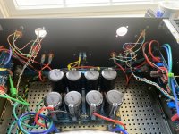
NOT FINAL WIRE MANAGEMENT...I am keeping things long until I get the placement the way I like, then I will trim and re-terminate.
I have identified the two pairs based on continuity (and it is logical based on how the wires disappear inside the transformer).
Assume it doesn't matter if the primary or secondary pairs are switched? I know I can't switch JUST the two reds or blacks, but could I swap the position of both pairs and it would give the same result. I need to admit I am not totally sure what is happening here, why just the outside-most connectors get the inrush limiter, and the center one gets the safety cap.
Thanks, and glad to be back in it!
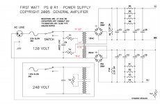
Both 120V windings are "primary" windings as they are on the input side. The "secondary" windings are the output windings.
Identifying the wires of the windings by continuity is correct.
Each primary winding has an inrush limiter. The safety capacitor is placed across the 120V line voltage. This can be seen on the power supply schematic.
Identifying the wires of the windings by continuity is correct.
Each primary winding has an inrush limiter. The safety capacitor is placed across the 120V line voltage. This can be seen on the power supply schematic.
Attachments
Also, can someone validate the 5A 10ohm version of the CL-60 is still the preferred choice? I also have the same part in 5A 20 ohms and recall debate saying the CL-60 might not be the best option (it is too fast). I would certainly prefer a slower, more gentle start. That said, I am not trying to pioneer anything here and am happy to use 'what everyone else is'. Thanks!
https://www.mouser.com/ProductDetail/527-CL60
https://www.mouser.com/ProductDetail/527-CL60
- Home
- Amplifiers
- Pass Labs
- Aleph J illustrated build guide