I was just trying to help out a fellow diyer.")
And at that you never fail. Thanks for the insight, formula noted.
Boky: I plan on using ice cubes to cool the caps, to keep ESR low. Wonder if they can take a bit of water.
Judging by this photo you posted, you'll need all the help you can get, so the idea is sound. Give them ice cubes a go - most definitely.
Jokes aside. I was thinking about pm’ing you today about your thoughts. All help appreciated, I am all ears. First P2P PSU.
Low ESR 100k’s at the end. 10uF’s MKP decouplers at the load/last set of caps.
Ground planes will mean as few wires as possible, but inductors of course need them.
Edit: last pic a few posts back have the caps more closely mounted. The small ones need some disrance from each other iot accomodate the ground planes.
Last edited:
Aleph J Dual Mono
Finally received the chassis from Italy, shipment was stuck in France for a week but arrived in Miami yesterday. Ready to start the Dual Mono Build, looking forward to it. I will post pictures as I go, will be slow start as I have a few Work trips coming up.
I also attached the latest Power Connection drawing, swapped the Connections on both Fuses (line input on center connection and Line out to side connection) thank ZenMod for the Comment.
Greeting from Sunny Miami,
Max
Attachments
Finally received the chassis from Italy, shipment was stuck in France for a week but arrived in Miami yesterday. Ready to start the Dual Mono Build, looking forward to it. I will post pictures as I go, will be slow start as I have a few Work trips coming up.
I also attached the latest Power Connection drawing, swapped the Connections on both Fuses (line input on center connection and Line out to side connection) thank ZenMod for the Comment.
Greeting from Sunny Miami,
Max
Man I'm jealous of how nice and tidy your workbench is. Happy building!
Brilliant. I have the tiniest of suggestions. It's mostly for the benefit of others since your work will likely be used by many that follow.
These old eyes with this monitor ... at this resolution ... at this distance saw a CL-60 across your mains live/neutral at the switch. Then I zoomed in to see that you had it labeled properly as your safety cap.
Would you consider changing the symbol / outline slightly and perhaps color it blue along with including the notation of X1/Y1. Many of those caps, but not all, that people order will be blue in color, and they do need to be mains safety rated.
Once again... just beautiful work. You've unknowingly likely helped a number of future DIYers.
Most importantly, start slinging some solder! Have fun, and enjoy the tunes.
Transformer/ Amplifier Board Distance Question
Hello All,
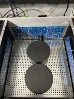
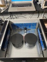
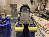
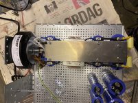
I started dry layout today for Dual Mono Aleph J, and I have a question regarding the distance between the Transformer and the Amplifier Board.
- Mounting the transformers side by side will be better for the wiring but the the transformer casing will be about 1 1/2 inch (38.1mm) away for the AMP PCB. (I can gain another 1/2" (12.7mm) if I use Shorter Stand-off behind the PCB and put the Transformer housings closer together)
- I also have the option to mount them back to back but wiring will be more complicated (see pictures)
- The transformers are both shielded (Antek - AS-2218) and will be mounted in a steel enclosure (Antek - AN-200)
I ordered a 5U Chassis and was thinking to use the extra height to elevate the Base Plate, this way I can run all power wiring below it and keep it away from the Electronics area.
Any input will be much appreciated.
Greetings from Miami.
Max
Hello All,
I started dry layout today for Dual Mono Aleph J, and I have a question regarding the distance between the Transformer and the Amplifier Board.
- Mounting the transformers side by side will be better for the wiring but the the transformer casing will be about 1 1/2 inch (38.1mm) away for the AMP PCB. (I can gain another 1/2" (12.7mm) if I use Shorter Stand-off behind the PCB and put the Transformer housings closer together)
- I also have the option to mount them back to back but wiring will be more complicated (see pictures)
- The transformers are both shielded (Antek - AS-2218) and will be mounted in a steel enclosure (Antek - AN-200)
I ordered a 5U Chassis and was thinking to use the extra height to elevate the Base Plate, this way I can run all power wiring below it and keep it away from the Electronics area.
Any input will be much appreciated.
Greetings from Miami.
Max
Attachments
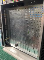
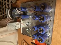
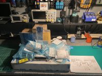
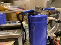
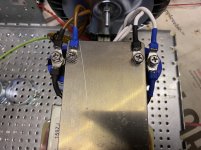
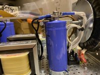
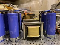
Since it is PSU day today, here is one DC section of my PSU prototype finished, sans chassis gnd/loop breaker.
Ripple is not my concern. Exciting stuff will be whether loops are under control. We will see. Intention was for 0v tapping section to be even further from the equalizing currents between last two caps, but other stuff dictated the distance. If noisy I just have to make a new ground plane, simple as that.
Also, due to same circumstances, bridge wires are a bit long. Maybe I’ll shorten later.
Anyways, for prototype, pretty happy.
After gnd is connected I will test under load. Excited about ripple, modelled to very low, lets see what the real world says. Also possible loop areas as well as inductors in line (but not imminently close) to amp circuitry. We will see
Quite a lot of gear stuffed into that space, kinda excited it all fits nicely.
Edit: been in the making inside my head for 7 months, so quite rewarding to finally see it. Will it work the wonders i hope? Maybe. If not, this is an excellent opportunity to learn and perfect. And if it’s not perfect first time around? Who the heck cares. I did this.
Regards
Andy
Attachments
-
 296ADE2B-AD2D-430B-B25F-1E9CB38C8020.jpeg235.9 KB · Views: 89
 -
 E2EBC6B6-E1CF-4CF1-898D-33F8A1C7D434.jpeg329.5 KB · Views: 90
 -
 AFA06C68-3705-4B90-B32E-91A1DFFD4E9C.jpeg284.9 KB · Views: 84
 -
 1D4D8CE4-A6A5-4144-8E90-69AF9A21EF7B.jpeg304.5 KB · Views: 93
 -
 9A0A6B0E-5902-47E6-AB4D-390793E97589.jpeg298.7 KB · Views: 132
 -
 16F8BAE7-82C4-4CBF-B96C-57590F680AF3.jpeg448.6 KB · Views: 136
Last edited:
I’ve just finished my Aleph J.
What beautiful sound!
I built a couple of ACAs which I really liked. This is big step up.
With the recommended 400mv bias I’m getting 52 - 53 degrees on the heatsinks with an ambient temperature of about 25 degrees. Probably slightly higher than ideal at that temperature, but within the bounds of ‘okay’? My enclosure is a Chinese sourced unit with heatsinks about ten per cent smaller than the 4U.
The only problem with the build occurred when turning the amp on for the first time. One channel was fine. The other: no current on the bias resistor. A heart sinking moment - crap! I’ve done it wrong, and I don’t know nearly enough to figure out what I’ve done wrong. Gathered my thoughts and checked the DC offset: yikes - 24 volts. Once I’d dialled that back all was well.
I cannot believe what a magical sound I’m getting. Holographic, crystal clear, yet not a hint of harshness. The Aleph J is driving a pair of Alpair 7MSs, with a Gainclone taking care of a pair of Jordan JX125s. I’m crossing over at 180Hz, using a MiniDSP.
Thanks to all who’ve contributed with advice and guidance, especially newbie power supply questions. And big thanks to Nelson Pass for such a gift of musical joy.
YES! I would love a 4U 400mm Deluxe chassis. I think it'd be perfect for 95% of the class A builds on DIY Audio, and that it'd be so popular that all the other sizes of Deluxe would become obsolete...just my 2 centsjust another reason to declare 4U/400 as main Store case

side by side, close to front
that is farther from signal inputs
just another reason to declare 4U/400 as main Store case
4U/300 is for Weaklingsesssss
Much obliged, Zen Mod.
I’ve just finished my Aleph J.
What a beautiful sound!
Sweet! Aleph Js are very nice.
The case looks good as well!. I really like the mains switch at the front.
Enjoy.
I’ve just finished my Aleph J.
What beautiful sound!
I built a couple of ACAs which I really liked. This is big step up.
View attachment 1001146
View attachment 1001147
Another great build, congrats
Enjoy the music
- Home
- Amplifiers
- Pass Labs
- Aleph J illustrated build guide