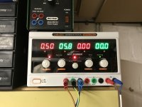
Setting up my bias and offset now and everything looks great !
Noticed that the discrete diodes in the power supply are quite warm at about 41deg C
Is that ok ?
they work on steam, so normal

Hi all, ive been listening to this lovely sounding creation for the past few months without a case and now im kind of worried my cat may take a shine to the heat and decide to sit on the bare wires.
I have also not installed a thermistor as I was unsure what value to use as its not clear on the schematic for us 240v lot here in the UK.
Can anyone recommend a thermistor value or an equation for a 240v UK supply that will help me please ?
many thanks
I have also not installed a thermistor as I was unsure what value to use as its not clear on the schematic for us 240v lot here in the UK.
Can anyone recommend a thermistor value or an equation for a 240v UK supply that will help me please ?
many thanks
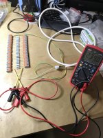
OK, wiring complete. Started the testing and adjusting.

PSU checked OK with both DC voltages at around 25.9V and -25.9V unloaded. Then I connected just one PCB and started biasing. Is it normal for the bias voltage over the resistor to drop as the amp heat up? Started at 400mV, but every now and then I have to adjust to get it back up. DC offset is about 0.006 mV. EDIT: Corrections are getting less and less as it heats up. Sinks are nice warm now after 30 minutes.
Once this PCB is done I am connecting the other PCB. Hope that channel goes as well as this one.
Last edited:
Hi all, ive been listening to this lovely sounding creation for the past few months without a case and now im kind of worried my cat may take a shine to the heat and decide to sit on the bare wires.
I have also not installed a thermistor as I was unsure what value to use as its not clear on the schematic for us 240v lot here in the UK.
Can anyone recommend a thermistor value or an equation for a 240v UK supply that will help me please ?
many thanks
I used a single CL60 with no issues yet.
Peppennino,
I’m not positive.. I’m out of town working until tomorrow, but I’ll find out tomorrow evening for you..
Cheers!
so, state of affairs as usual - ZM confused ......

did you get it operational - both channels?
what was with fuse situation?
@henryve, yes, it's normal for the bias voltage to drop when the amp heats up. Check the initial voltage to be sure that it is not too high and then close the lid and let the amp to reach it's normal working temprature (wait for at least 30 min., perhaps an hour). And then open the lid and set the bias.
I have also not installed a thermistor as I was unsure what value to use as its not clear on the schematic for us 240v lot here in the UK.
Can anyone recommend a thermistor value or an equation for a 240v UK supply that will help me please ?
As there were talks in the forums that a single CL60 has too low cold resistance (11ohm) for 230V, I had made my initial search when building my first FW clone and I used SL15 47003 for all 3 that I made. No blown fuses on start up so far. It has 47ohm initial resistance. 0.77ohm at 1.5A current. I lose about 1V on it when it's hot. Works well for me.
SL15 47003
I am not an expert though. So take it for what it's worth.
Last edited:
Pass DIY Addict
Joined 2000
Paid Member
I am playing the MOSFETs matching game. Ordered a tube (25 units) of IRFP240...
Does all this makes any sense (without any thermal measurement/control)?
How long should I wait before taking the Vgs measurement?
Or is all this just monkey business?
Alvis: My findings pretty much match you own. Long ago I measured a bunch of these for my big Aleph-X amps, each amp runs 12 output mosfets. The general advice is to measure them at the voltage/current levels that they will see in the completed amp (close to 1.5A each). But, my bench supply could only only provide 1A at 22v. So, I measured them at a number of voltage and current combinations. What I found is that measuring them for 30-45s was plenty to group them accurately. I also found that once grouped by voltage measurement as you show, the groupings tend to hold up well at different voltage and/or current combinations. I had a number of them that matched to within 3-5mV on the bench. I also matched my source resistors. In the complete amp, the transistor bias and dissipation measurements are near perfect matches.
The keys points were to measure them all in the same sitting (same temp environment) and to measure them at precisely the same time interval since the voltage will change as they heat up. Essentially any "reasonable" voltage and current combination will reveal useful matches.
More details are in my big Aleph-X page that is linked in my signature. Scroll down to the "Matching Mosfets" section.
She's making music mama!
Spinning Dire Straits's Alchemy on the Linn at the moment.

Congrats! I see you used Andrew Russell's method of breaking up a ground loop! Well done!
Do you have dual heatsinks on each side? Or single? What bias did you settle on, 0.85A (400mV) or 1.06A (500mV)? I have found 0.85A for single heatsink (4U/300 chassis) is safest.
Thanks,
Anand.
Last edited:
She's making music mama!
Spinning Dire Straits's Alchemy on the Linn at the moment.
Congrats! I see you used Andrew Russell's method of breaking up a ground loop! Well done!
Do you have dual heatsinks on each side? Or single? What bias did you settle on, 0.85A (400mV) or 1.06A (500mV)? I have found 0.85A for single heatsink (4U/300 chassis) is safest.
Thanks,
Anand.
My case is the 4U/400, in other words it has 2 sinks per side. I have settled for now on 400mV bias since it can get toasty around here. Even now in late April we still get the occasional 30 degrees C day.
Last edited:
I tried to upload the pdf—but it's too big.
Try this here.
First link on the page to PDF, after a little scroll...
Try this here.
First link on the page to PDF, after a little scroll...
The keys points were to measure them all in the same sitting (same temp environment) and to measure them at precisely the same time interval since the voltage will change as they heat up. Essentially any "reasonable" voltage and current combination will reveal useful matches.
More details are in my big Aleph-X page that is linked in my signature. Scroll down to the "Matching Mosfets" section.
Thanks, Eric. Read your page with interest.
Measuring Mosfets at 170mA was easy. Doing this at 850mV would be much more trouble. I'll hope they will be matched at higher current as well as they were on lower current. I'll see the results when I have time to re-solder mosfets in my board.
Pass DIY Addict
Joined 2000
Paid Member
She's making music mama!
Spinning Dire Straits's Alchemy on the Linn at the moment.
Evviva!

Put away the meters and buona musica!


... I also matched my source resistors. In the complete amp, the transistor bias and dissipation measurements are near perfect matches.
The keys points were to measure them all in the same sitting (same temp environment) and to measure them at precisely the same time interval since the voltage will change as they heat up. Essentially any "reasonable" voltage and current combination will reveal useful matches.
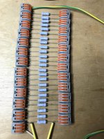
I second that matching source resistors is important, especially if you are using +/- 5% resistors.
Have a look at my technique of matching source resistors. The usual multimeters and measurement techniques are very bad at measuring low resistances, but are quite accurate in measuring tiny voltages
Best regards, Claas
Attachments
- Home
- Amplifiers
- Pass Labs
- Aleph J illustrated build guide