happy friday night
just wanted to say thanks to a great DIY community right here, was able to build a fantastic sounding Aleph J amp on my own with your help and build confidence for other projects..Most Respects to Papa Nelson for his generosity and the great community right here!
just wanted to say thanks to a great DIY community right here, was able to build a fantastic sounding Aleph J amp on my own with your help and build confidence for other projects..Most Respects to Papa Nelson for his generosity and the great community right here!
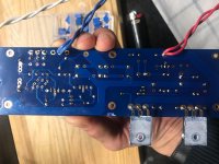
Wanted to share some photos, at a bit of a loss, will remove and test MOSFETs in AM. But so far, have checked and replaced both trim resistors, new JFETs from the Store, new Q2, Q3, Q4 - etc, etc,
Any input is appreciated,
For reference, I'm just getting some sort of short, bulb dims momentarily and then goes fairly bright again. I cut power aggresively, other channel has been flawless from the get-go.
Any input is appreciated,
For reference, I'm just getting some sort of short, bulb dims momentarily and then goes fairly bright again. I cut power aggresively, other channel has been flawless from the get-go.
Attachments
Wanted to share some photos, at a bit of a loss, will remove and test MOSFETs in AM. But so far, have checked and replaced both trim resistors, new JFETs from the Store, new Q2, Q3, Q4 - etc, etc,
Any input is appreciated,
For reference, I'm just getting some sort of short, bulb dims momentarily and then goes fairly bright again. I cut power aggresively, other channel has been flawless from the get-go.
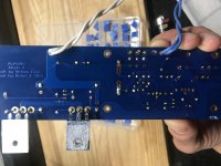
Q2 is BC550C or ZTX450?
Q3 and Q4 seems like ZTX and Q2 seems like BC.
They have different pinout.
Attachments
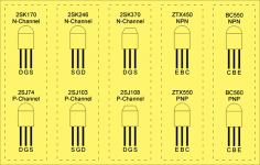
2. Q2 is the MPSA92, just confirmed
Oh I just saw.
And Q2 is BC560C / ZTX550
Sorry for error.

Last edited:
Thanks for the looks - after a marvelous amount of meticulous desoldering and checking - it looks like i've got a failed C5 - 5pF.
I dont have any spares on hand - I've got some 1nF, which is the closest ive got.
I could also de-solder the good one from the good board and see if that alleviates the problem.
I dont have any spares on hand - I've got some 1nF, which is the closest ive got.
I could also de-solder the good one from the good board and see if that alleviates the problem.
I was hoping I could edit the last post but alas.
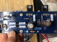
Have spent most of the day on this to little/no avail:
Prexisting condition - bulb test goes way bright!
Things I have done:
- Checked part, solder, etc.
- Replaced JFETs with fresh ones from Store, though the pair I had are "OK"
- Desoldered MOSFETs and tested those with Mega328 tester, all "OK" resoldered those, mounted, continuity check etc.
- Checked and Replaced 450 and MPSA92 diodes.
- Checked every cap, all good
- Checked every resistor - didnt desolder each one, but checkd values etc.
Power up landscape - I have nothing connected to inputs, nor the out of the amp board, just GND, V+ and V- coming in.
I just now powered up with a DC variable PSU I have, maxes out at 24V @ 5A, but in observation my bias pot "maxes out" before I can get the DC Offset anywhre reasonable. Started around 2V, and continues to drop - best case I can get it below 100mv @ 12V or so, but as the voltage gets applied, it climbs up as well.
Measuring Bias across resistors has been intersteing - very HIGH bias, without any effect from trimming pot R27 - I can turn it all I want, no change, this strikes me as the best indicator of what may be happening, but at this point, id rather let the experts here chime in.
FWIW, the other channel, is "perfect" and PSU tested great before and while powering it, with rails at about +/- 24.8V
Some measurements for you:
Source (DC PSU)
30.86v, 1.09A, 33W
Across R8 - 8.58v
Across R7 trim - 4.25v
Across D1 - 9.2v
Output offset (VDC)
-.002v (negative, adjustable with trim to 0)
R16 - .267v
R17 - .245v
R19 - .266v (slow climb, maybe related to no input, settled here)
R18 - .247v
R27 trim - 1.98v
Heatsinks are warming up, been on or about 15, going to let us sit a bit longer and check readings then. seems "stable" for whatever thats worth
why not putting it to work at prescribed +/- voltage ?
there is one caveat, when using lab supply - you must remember to set Current limits above circuit demand (for proper operation) and you must be sure in proper behavior of said Lab Supply
will try to wrap my head around your list and schm on first page, tomorrow
just in case, often not remembering to remind on trivia - mosfets well isolated from heatsink, all resistors in place, no flipped active parts ....... ?
inputs grounded, no load on output, bulb tester ( if used ) just for unloaded PSU testing etc.
and - there is nothing wrong with temporary placed fast fuses in rails , while doing it for first time
Thank you ZM,
Yes confirmed across the board - I used the Lab PSU, just to take those measurements, since the dim bulb limits voltage to 18V from V+ to V-
Interestingly the "good board" shows zero bias across any resistor when connected to lab PSU.
For clarity - inputs shorted you mean short from input - to input +?
Im honestly an hour away from ordering a new set of boards and parts, i've been my usual meticulous self, but this one seems to be creating all sorts of issues for me,
UPDATE - the "bad" board is good. Now to see whats up with the "good board" maybe we do have damaged JFETs here. Thank you all for your infinite patience
Last edited:
inputs grounded, which means both + and - input connected to GND
you can't do nothing with bulb tester ........ point is - even if you succeed to set it partially ( because bulb tester is limiting rails voltage ), after you remove it ( bulb tester) and power up again, everything is just going BigBadaBoom!
reason - amp underbiased with low rails becomes overbiased with full rails
so, proper procedure is mandatory - bulb tester only for conforming that PSU is functional ( unloaded) and maybe initial test with channel(s) connected with PSU, but after that you must remove bulbie thing
if you did everything by the book, nothing will gto south and you'll set it , more or less easy
if you didn't ..... well , you'll learn something ....... if nothing else, than - lack of mileage is most easily compensated with money - always buy double or triple , of things you're able to transform in gray smoke
again - nothing wrong with temporary placed fuses in both rails; say that F2A5 is good value
JFets - only sure way of checking is either in circuit ( mileage, again) or in simple "matching jig"
same applies for mosfets ...... little Gizmos with displays are good, as informal tool, and I'm using it every day ...... but only in that manner - as informal tool
when I'm in doubt, elbow grease is way to solve it, if I already didn't pony up for special Gizmos with BigBadA$$Display
You are wise, ZM.
Applied full voltage to rails and all is behaving as it should.
The other board needs some TLC, but I’ve been so focused on the “bad one.” I think I just got spooked and now I’m being perhaps too careful? Anyways, comforting to know the diligence paid off on this board, will dig into the other feeling confident I can sort it.
Will update!

 to your progress, keep us informed and remember - No Porn, No Glory
Hi. Seeking comments from the wise men.
I tried to measure the input sensitivity of my Aleph J on the range of the output levels. And this is what I got:
0.27V in -> 2.83V out (1W/8ohm), gain 19.6 dB
0.97V in -> 8.94V out (10W/8ohm), gain 19.3 dB
1.09V in -> 10.83V out (12W/8ohm), gain 19.1 dB
1.26V in -> 10.95V out (15W/8ohm), gain 18.8 dB
1.85V in -> 14.14V out (25W/8ohm), gain 17.7 dB
I noticed that gain started to drop above ~12W. As I did not have this effect on my other FirstWatt clones (F5 and M2X), I got suspicious and started to doubt that my Aleph cannot make to the prescribed 25W.
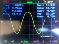
I only have a "toy" oscilograph (DSO shell), but I tried it anyway.
And here are the pictures attached.
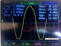
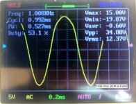
At 10W, everything looks fine.
At 15W, the sine becomes a bit distorted.
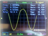
At 20W, the positive part of the sine is clearly fatter than the negative.
At 25W, it clips.
I also did not like the difference in amplitude of the Vmax and Vmin. Does it tell anything?
And what would you say in general?
Is it just normal behaviour and the distortion of the sine just tells the increasing THD with increased power?
Is clipping at about 22-25W (on 8ohm load) is also normal? (as my parts clearly are not so good as Papa's).
Or is my equipment just total crap and my measurements do not make any sense and are not worth the effort?
I would be glad to learn from that.
-Alvis
I tried to measure the input sensitivity of my Aleph J on the range of the output levels. And this is what I got:
0.27V in -> 2.83V out (1W/8ohm), gain 19.6 dB
0.97V in -> 8.94V out (10W/8ohm), gain 19.3 dB
1.09V in -> 10.83V out (12W/8ohm), gain 19.1 dB
1.26V in -> 10.95V out (15W/8ohm), gain 18.8 dB
1.85V in -> 14.14V out (25W/8ohm), gain 17.7 dB
I noticed that gain started to drop above ~12W. As I did not have this effect on my other FirstWatt clones (F5 and M2X), I got suspicious and started to doubt that my Aleph cannot make to the prescribed 25W.
I only have a "toy" oscilograph (DSO shell), but I tried it anyway.
And here are the pictures attached.
At 10W, everything looks fine.
At 15W, the sine becomes a bit distorted.
At 20W, the positive part of the sine is clearly fatter than the negative.
At 25W, it clips.
I also did not like the difference in amplitude of the Vmax and Vmin. Does it tell anything?
And what would you say in general?
Is it just normal behaviour and the distortion of the sine just tells the increasing THD with increased power?
Is clipping at about 22-25W (on 8ohm load) is also normal? (as my parts clearly are not so good as Papa's).
Or is my equipment just total crap and my measurements do not make any sense and are not worth the effort?
I would be glad to learn from that.
-Alvis
Attachments
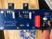
Just wanted to share an update and express some success, thanks to the patient minds here, and my all but frustrated self!
While I'll never know what the issue was with the bad board, to be honest, I went over it so many times I lost sight of what it might have been. I can tell you what it wasnt, which was my JFETs or MOSFETs.
The "good board" was operating normally, but not biasing - turning out to be a bad pot in position R27, which I mistakenly replaced with a 100K that didnt get me the desired results, only to realize that 200K is appropriate.
I did find that feeding the boards with a lab supply allowed me to more peacefully work the issues out, FWIW!
Followed most of Extreme_Bokys mods here, ommitted R13, 14 and Q3, as well as bridged C1. Currently no C6/7 since they are OOS of the right spec. I biased it to 490mv and getting a nice 0.0 of DC offset. Left it on overnight, just a quick test and it sounds great so far, about to put her in the new home proper.
Possibly considering adding a bi-polar cap to PSU board if thumps prove to be an issue, have ordered some along with another project's parts in case that's a needed change!
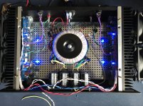
Built in a 3U case nice and tidy, need to clean up the wires to the PSU as you can see. I also found these super quiet 120MM fans that can be daisy chained and triggered by the power strip. They keep it all very cool and they are dead quiet. So, food for thought!
Lastly, I ended up ordering 20 Toshiba JEFTs with Punky on eBay, planning on building a matching jig and will likely offer them up at cost to other DIYers since I wont need that many for a while!
Comments, concerns, criticisms and all welcome!
While I'll never know what the issue was with the bad board, to be honest, I went over it so many times I lost sight of what it might have been. I can tell you what it wasnt, which was my JFETs or MOSFETs.
The "good board" was operating normally, but not biasing - turning out to be a bad pot in position R27, which I mistakenly replaced with a 100K that didnt get me the desired results, only to realize that 200K is appropriate.
I did find that feeding the boards with a lab supply allowed me to more peacefully work the issues out, FWIW!
Followed most of Extreme_Bokys mods here, ommitted R13, 14 and Q3, as well as bridged C1. Currently no C6/7 since they are OOS of the right spec. I biased it to 490mv and getting a nice 0.0 of DC offset. Left it on overnight, just a quick test and it sounds great so far, about to put her in the new home proper.
Possibly considering adding a bi-polar cap to PSU board if thumps prove to be an issue, have ordered some along with another project's parts in case that's a needed change!
Built in a 3U case nice and tidy, need to clean up the wires to the PSU as you can see. I also found these super quiet 120MM fans that can be daisy chained and triggered by the power strip. They keep it all very cool and they are dead quiet. So, food for thought!
Lastly, I ended up ordering 20 Toshiba JEFTs with Punky on eBay, planning on building a matching jig and will likely offer them up at cost to other DIYers since I wont need that many for a while!
Comments, concerns, criticisms and all welcome!
Attachments
Last edited:
Hi. Seeking comments from the wise men.
I tried to measure the input sensitivity of my Aleph J on the range of the output levels. And this is what I got:
0.27V in -> 2.83V out (1W/8ohm), gain 19.6 dB
0.97V in -> 8.94V out (10W/8ohm), gain 19.3 dB
1.09V in -> 10.83V out (12W/8ohm), gain 19.1 dB
1.26V in -> 10.95V out (15W/8ohm), gain 18.8 dB
1.85V in -> 14.14V out (25W/8ohm), gain 17.7 dB
I noticed that gain started to drop above ~12W. As I did not have this effect on my other FirstWatt clones (F5 and M2X), I got suspicious and started to doubt that my Aleph cannot make to the prescribed 25W.
I only have a "toy" oscilograph (DSO shell), but I tried it anyway.
And here are the pictures attached.
At 10W, everything looks fine.
At 15W, the sine becomes a bit distorted.
At 20W, the positive part of the sine is clearly fatter than the negative.
At 25W, it clips.
I also did not like the difference in amplitude of the Vmax and Vmin. Does it tell anything?
And what would you say in general?
Is it just normal behaviour and the distortion of the sine just tells the increasing THD with increased power?
Is clipping at about 22-25W (on 8ohm load) is also normal? (as my parts clearly are not so good as Papa's).
Or is my equipment just total crap and my measurements do not make any sense and are not worth the effort?
I would be glad to learn from that.
-Alvis
1. Try adjusting the bias (quiescent current) and see if the symmetry improves.
2. Lift one end of R13 (disable the short protection) and see if that helps.
3. What are your power supply rails? I chose the transformer so that with 2A bias (per each AMP PCB) -> I still have + and - 24V. Sometimes I get 25V - depending on the mains supply.... The JFET's seem to be doing okay.
- Home
- Amplifiers
- Pass Labs
- Aleph J illustrated build guide