If you use Euroblock ("Luesterklemmen") connectors, the correct process according to the rules for trades people (electrians) are to use either:
- single-core wire, or
- if using Litz wire, crimp a ferrule over it before inserting it into the Euroblock
Do not use tinned wire, because the tin / solder very slowly "flows" with the pressure of the connector, becoming loose over time.
Also, if you would fastening Litz without ferrules, the screw tends to cut away some of the small wires, resulting in an insecure connection as well.
Have seen both problems in house installations myself , where here in Germany Euroblocks used to be used extensively ...
I have bought a kit with ferrules and a crimping tool and always use ferrules for the Euroblocks with Litz wire ...
With the board-attached screw connectors that have a small "flap" between screw and inserted wire, on the other hand, raw Litz without treatment (just twist together before inserting) works best.
Hope this helps,
Claas
you did right - comparing new one with suspicious
buzzing and conducting in all directions is sure sign of Dodo mosfet
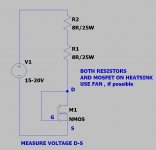
Suppose I need to match up some new mosfets. I'm going to use the "test everything circuit" to get started, or the "real life test setup" if I have the parts on hand.
One question though is about the AC source. Is this supposed to represent an input signal? What can be used for the AC source? Sorry for the nube questions - I'm a recent tube amp transplant into the world of SS amplifiers.
Mosfet measuring/matching
here
you can use laptop brick PSU
calc resistor string as (Urail - 4V)/I = R [Ohms], where I is your desired matching current
example :
standard brick , U=19V
I= 800mA (say that's for Aleph J situation)
that means resistor(s) in drain needs to be
(19V-4V)/0A8=18R75
be creative and use standard value resistors, combine
say that you have 10R resistors at hand, so two in series are 20R, close enough
dissipation at resistors sum will be P=I^2 x R
so 0A75^2 x 20R= 11W25 ........ so two proper 10R/10W resistors will do the job, even if stroner ones (possibly heatsinked ones) are better - you'll wait less for stable readout
Attachments
Sudden 120Hz loud hum in right channel
Hello,
I need some help with the Aleph J amp I completed about a week ago with help from forum member Rhing, the document created by 6L6, the DIY Implementer video on Youtube, and many other helpful posts on the forum.
Everything worked great the first time I turned on the completed amp. After breaking in for a few days, I really like how the amp sounds.
A couple day ago, the right channel of the amp started humming loudly as I turned it on. It makes little difference whether the RCA input to the amp is grounded or not, or if there is any input at all.
These are some of the things I've observed about the amp.
1. Using a spectrometer on my phone, I found the main component of the hum is around 120Hz.
2. There has always been a soft pop when the amp is turned on and a loud cracking sound when turned off. Today, I measured the max “cracking” voltage across the speaker terminals when the amp was turned off, the left was at 3.1 volts, and the right 6.6 volts.
3. When the amp was working with no problem the bias reading on R16, R17, R18, R19 for the left channel in mV were 400, 384, 396, and 399, respectively. The right channel 382, 369, 399, and 352, again respectively. The bias readings on the left had less variance than right channel, especially for R18 and R19. Not sure if this is an issue.
4. Today, the bias reading on R16, R17, R18, R19 of the right channel are between 350mV to 400mV. As they are all passing current, I presume that the MOSFET are working ok.
5. I have checked for cold joints and loose connections but couldn’t find any.
6. I can still hear music coming through the right channel together with the hum, but the volume is lower and the sound is distorted.
7. Small adjustment in the bias results in a large change in offset value and vice versa, making it impossible to set the bias and offset to the desired values.
Any help to determine the cause of the problem will be appreciated.
Awajoy
Attachments
![IMG_3643[1].JPG](/community/data/attachments/810/810315-e798c0b26050728052dc284ef596c845.jpg)
![IMG_3642[1].JPG](/community/data/attachments/810/810328-08a0ccf0e8f2750a64cd4c526048595e.jpg)
![IMG_3629[1].JPG](/community/data/attachments/810/810335-04e3e433f17952edcce7a3f7f51e655f.jpg)
![IMG_3646[1].JPG](/community/data/attachments/810/810345-851dfbab3b47d3b628dc2f634e37181d.jpg)
How to mount the front panel on Modushop enclosure
I didn’t know where else to post this- but as a noob AJ builder I thought this was just as well.
I’m having a hard time mounting the front plate onto the the enclosure. The holes in the black front plate seem too far apart to be attached to the brackets affixed to the heat sinks. See enclosed photo: only one hole on a side in the front piece fits in the mounting brackets- not both. Also the hole is shallower than any of the screws that come with- does one need to use a couple nuts? Any ideas?
And some day I’d like to use a nice piece of wood instead of the metal- anyone done that?

TIA,
I didn’t know where else to post this- but as a noob AJ builder I thought this was just as well.
I’m having a hard time mounting the front plate onto the the enclosure. The holes in the black front plate seem too far apart to be attached to the brackets affixed to the heat sinks. See enclosed photo: only one hole on a side in the front piece fits in the mounting brackets- not both. Also the hole is shallower than any of the screws that come with- does one need to use a couple nuts? Any ideas?
And some day I’d like to use a nice piece of wood instead of the metal- anyone done that?
TIA,
Hello,
I need some help with the Aleph J amp I completed about a week ago with help from forum member Rhing, the document created by 6L6, the DIY Implementer video on Youtube, and many other helpful posts on the forum.
Everything worked great the first time I turned on the completed amp. After breaking in for a few days, I really like how the amp sounds.
A couple day ago, the right channel of the amp started humming loudly as I turned it on. It makes little difference whether the RCA input to the amp is grounded or not, or if there is any input at all.
These are some of the things I've observed about the amp.
1. Using a spectrometer on my phone, I found the main component of the hum is around 120Hz.
2. There has always been a soft pop when the amp is turned on and a loud cracking sound when turned off. Today, I measured the max “cracking” voltage across the speaker terminals when the amp was turned off, the left was at 3.1 volts, and the right 6.6 volts.
3. When the amp was working with no problem the bias reading on R16, R17, R18, R19 for the left channel in mV were 400, 384, 396, and 399, respectively. The right channel 382, 369, 399, and 352, again respectively. The bias readings on the left had less variance than right channel, especially for R18 and R19. Not sure if this is an issue.
4. Today, the bias reading on R16, R17, R18, R19 of the right channel are between 350mV to 400mV. As they are all passing current, I presume that the MOSFET are working ok.
5. I have checked for cold joints and loose connections but couldn’t find any.
6. I can still hear music coming through the right channel together with the hum, but the volume is lower and the sound is distorted.
7. Small adjustment in the bias results in a large change in offset value and vice versa, making it impossible to set the bias and offset to the desired values.
Any help to determine the cause of the problem will be appreciated.
Awajoy
PSU common for both channels or dual mono?
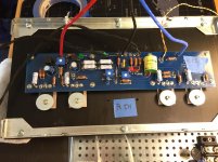
in any case, dismantle that pcb from heatsink and inspect all solder joints
post well lit and big enough pics here
I didn’t know where else to post this- but as a noob AJ builder I thought this was just as well.
I’m having a hard time mounting the front plate onto the the enclosure. The holes in the black front plate seem too far apart to be attached to the brackets affixed to the heat sinks. See enclosed photo: only one hole on a side in the front piece fits in the mounting brackets- not both. Also the hole is shallower than any of the screws that come with- does one need to use a couple nuts? Any ideas?
And some day I’d like to use a nice piece of wood instead of the metal- anyone done that?
View attachment 894993
TIA,
tried to move front plate up?
holes in front are lining in inner ends of bracket slots
Argqsys - Wherever you read that, it’s not correct. The Aleph 3 has a mosfet voltage gain stage and an extra pair of output mosfets, the Aleph J has a Jfet voltage gain stage. They are very similar electrically, and almost identical operationally.
Lonepine510 - The front panel attaches to the brackets with the bigger holes in your photo.
Awajoy - Do you have pin 1 jumpered to pin 3 in the XLR when using RCA? Or are you feeding the amp with signal from XLR only?
Lonepine510 - The front panel attaches to the brackets with the bigger holes in your photo.
Awajoy - Do you have pin 1 jumpered to pin 3 in the XLR when using RCA? Or are you feeding the amp with signal from XLR only?
Last edited:
Sudden 120Hz loud hum in right channel
PSU is common for both channels.
Pin 1 is jumped to pin 3 in the XLR at the back of the amp. I am using RCA only.
Will post better pictures later.
PSU common for both channels or dual mono?
in any case, dismantle that pcb from heatsink and inspect all solder joints
post well lit and big enough pics here
Awajoy - Do you have pin 1 jumpered to pin 3 in the XLR when using RCA? Or are you feeding the amp with signal from XLR only?
PSU is common for both channels.
Pin 1 is jumped to pin 3 in the XLR at the back of the amp. I am using RCA only.
Will post better pictures later.
PSU is common for both channels.
Pin 1 is jumped to pin 3 in the XLR at the back of the amp. I am using RCA only.
Will post better pictures later.
@Zen Mod, Hope these pictures are more helpful than the ones before.
Attachments
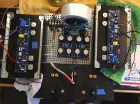
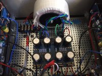
if you're not using balanced, then jumper negative input to gnd directly at pcb, then route twisted pair for positive and gnd to RCA ; bridge that to XLR input if you like
as you made it , positive signal wire is pretty lonely going from RCA to pcb, prone to collect noise
as you made it , positive signal wire is pretty lonely going from RCA to pcb, prone to collect noise
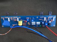
Awajoy - you have the RCA ground attached directly to chassis... I.E., on the wrong side of the ground-lift thermistor. That needs to be on PSU ground.
But before changing that, try wiring the RCA directly to the amp PCB (bypassing XLR) and jumper -IN to GND at the amp board inputs.
But before changing that, try wiring the RCA directly to the amp PCB (bypassing XLR) and jumper -IN to GND at the amp board inputs.
you can read all sorts of wisdom on internet

Thanks for your valuable support.
I didn’t know where else to post this- but as a noob AJ builder I thought this was just as well.
I’m having a hard time mounting the front plate onto the the enclosure. The holes in the black front plate seem too far apart to be attached to the brackets affixed to the heat sinks. See enclosed photo: only one hole on a side in the front piece fits in the mounting brackets- not both. Also the hole is shallower than any of the screws that come with- does one need to use a couple nuts? Any ideas?
And some day I’d like to use a nice piece of wood instead of the metal- anyone done that?
View attachment 894993
TIA,
I have assembled a few of their cases now. I learned not to tighten the bolts until I have fitted the pieces together. There is play here and there. In particular the rails on the top and bottom of the heat sinks can deform when tightened to the heat sinks. Leave just enough play under the screws until the front and back are on. Then try to square things up and then tighten everything. Even then, the top and bottom plates need finesse sometimes.
I ordered new front plates for my current monoblocks, so I will get another taste of this next weekend.
- Home
- Amplifiers
- Pass Labs
- Aleph J illustrated build guide