Application here is an Aleph J that started out with a single CRC diyAudio store board then went to dual mono still using diyAudio CRC boards.
OK, I give in - a second transformer is on order.

I just hope there's a chiropractor on hand when I try to pick up the finished amp!
Alternate Input Wiring for Reduced Hum and Noise
When I finished by Aleph J back in May, I intended to use it only in single-ended mode so I wired it according to the build guide. While I achieved 70-80 microVolts of hum/noise with inputs shorted, I had 100-200 microVolts when connected to my B1, B1 Korg preamps or directly to my Bel Canto DAC3. Not terrible, but not within factory spec of the commercial version. After some though, I decided to wire it up the inputs as balanced and found mbrenna's post, #4971, where he referenced a great document by Rane Commercial about grounding protocol.
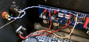
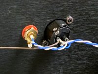
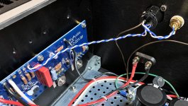
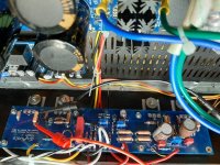
So, following mbrenna's and Rane's recommendation, I came to the following wiring scheme which gave me 70-80 microVolts of hum/noise with inputs shorted and with preamps/DACs connected:

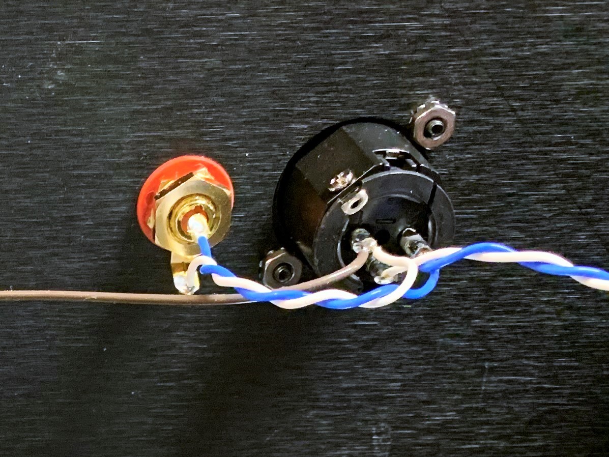
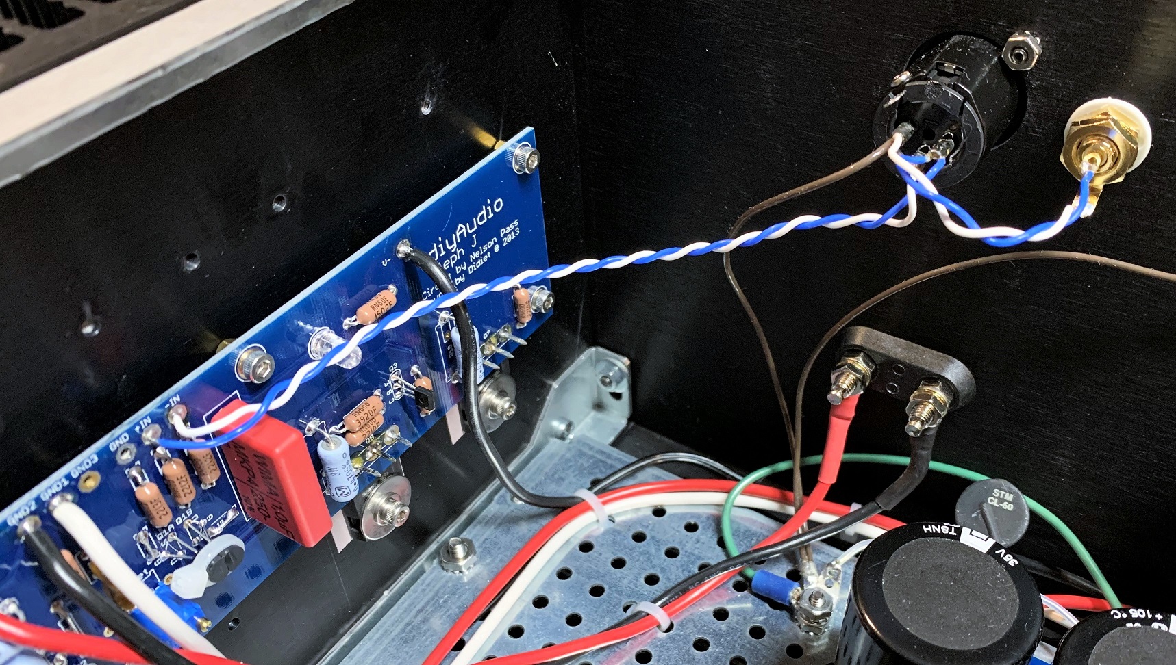
Key is to run a twisted pair of the plus and minus signal to the inputs and ground the XLR ground or single ended ground at the cable entrance. See the Rane document for more info. Now I have a very quiet amp and did not have to resort to cutting traces as some have done to reduce hum.
When I finished by Aleph J back in May, I intended to use it only in single-ended mode so I wired it according to the build guide. While I achieved 70-80 microVolts of hum/noise with inputs shorted, I had 100-200 microVolts when connected to my B1, B1 Korg preamps or directly to my Bel Canto DAC3. Not terrible, but not within factory spec of the commercial version. After some though, I decided to wire it up the inputs as balanced and found mbrenna's post, #4971, where he referenced a great document by Rane Commercial about grounding protocol.
So, following mbrenna's and Rane's recommendation, I came to the following wiring scheme which gave me 70-80 microVolts of hum/noise with inputs shorted and with preamps/DACs connected:
Key is to run a twisted pair of the plus and minus signal to the inputs and ground the XLR ground or single ended ground at the cable entrance. See the Rane document for more info. Now I have a very quiet amp and did not have to resort to cutting traces as some have done to reduce hum.
Attachments
OK, I give in - a second transformer is on order.
I just hope there's a chiropractor on hand when I try to pick up the finished amp!
The difference is not small, and immediately noticeable.
Russellc
OK, I give in - a second transformer is on order.
I just hope there's a chiropractor on hand when I try to pick up the finished amp!

Why just one, when two's more fun?
I hear you, best review proper lifting techniques.
Of all my amps ( Williamson 6L6's , F5 mono blocks, odd watt 6BQ5 ) my Aleph J is my go to amp. There is just something about that sound.
I agree, it is much more subtle than my Aleph 4. I love it.
I've got mine running with a single 625VA transformer but dual supplies.
It still sounds better than my Aleph 4 monoblocks.
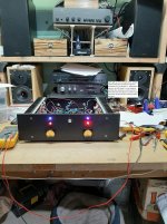
You can see the Aleph 4 in the background of photo 2.
Attachments

Last edited:
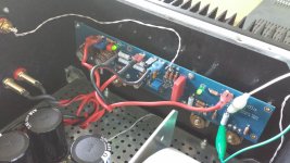
My Aleph J has double mono schematics in common case. It has 2 separate 150VA transformers 2x24V 3A. PS boards has 176000uF per channel. Bias is 1.7A. Transformers are hot, but not overheat. There is no humm or buzz present.
So, imho, 150VA per channel is quite enough for the Aleph J. Increasing the power will increase size, weight and spent money.
So, imho, 150VA per channel is quite enough for the Aleph J. Increasing the power will increase size, weight and spent money.
I thought it was noted that a single 300va was even slightly more than needed. The dual mono 200va build I just finished is also working great with 8x 15kuF per psu.
Going back to 6L6s bias adjustment guide in the first page, .4V is about .85A per mosfet device. Multiply that by your rail voltage under load to get power and you'll likely get something like 75-100 watts. Going 2X that would be pretty reasonable. Similarly, I thought someone mentioned using 7-8X output power per channel to size a transformer. This gives pretty much the same answer using 25wpc.
Hopefully I got that right, if not someone please correct me
My Aleph J has double mono schematics in common case. It has 2 separate 150VA transformers 2x24V 3A. PS boards has 176000uF per channel. Bias is 1.7A. Transformers are hot, but not overheat. There is no humm or buzz present.
So, imho, 150VA per channel is quite enough for the Aleph J. Increasing the power will increase size, weight and spent money.
1.7A is below spec isn't it.
My vague recollection is that it was meant to biased at 2A or possibly higher.
Obviously you can bias lower if you want.
I personally feel the time in labour spent building amps is significant enough that it's just not worth buying the bare minimum requirements, if for not a lot more money you can get something quite a bit better.
I thought it was noted that a single 300va was even slightly more than needed. The dual mono 200va build I just finished is also working great with 8x 15kuF per psu.
For F5 300VA is appropriate
If you're biased at 2A.
300VA for stereo is not really appropriate.
I agree, it is much more subtle than my Aleph 4. I love it.
I've got mine running with a single 625VA transformer but dual supplies.
It still sounds better than my Aleph 4 monoblocks.
You can see the Aleph 4 in the background of photo 2.
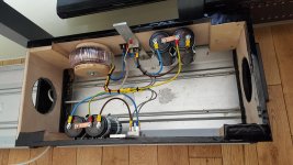
Aleph J is very nice looking. What is that audiostand your equipment, turntable etc. are on?
Russellc
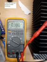
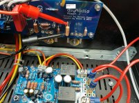
Any insight would be helpful. Thanks upfront. Speaker output jacks are reading about -17VDC. with Positive meter lead on the plus speaker terminal. This is measured at the board output location also which is why reading is same at terminal. Output bias pot seems to work. Both heat sinks get very warm and bias at about .0380VDC. NO amount of turns seem to affect the offset R7 to the left right channel speaker terminals. Found in build notes of turn pot till you get 0.0 VDC offset. At this point waiting for new output transistor thermal pads to remove boards and replace Bourns pots as a start. See schematic and was able to measure about 4.26VDC across R16 and R9. Used 10 watt dummy load to speaker outputs and wow heated up in a hurry. Glad did not use good speaker to test out. Anyway assuming a common build error on both channels on my part.
Attachments
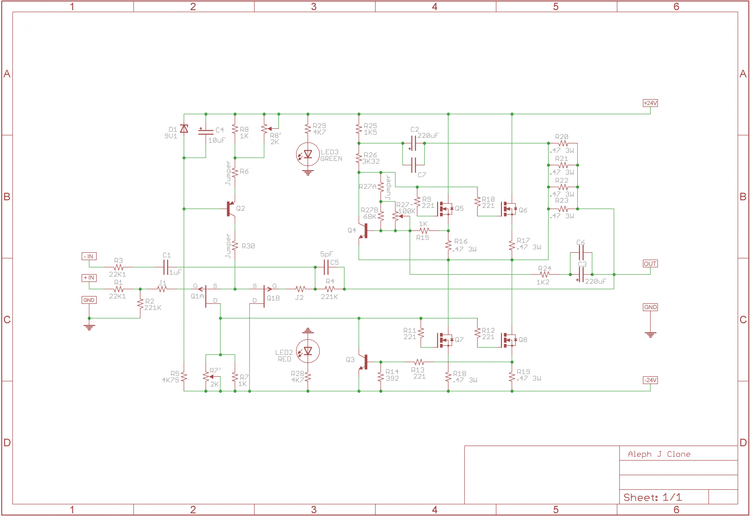
I'm going to refer to the schematics for the PCB as shown on page 1 of this thread:
https://www.diyaudio.com/archive/gallery/data/500/AJ_Sch.png
You seem to have resistors in the a number of the jumper locations, in particular R6 and R30.
What resistance values did you populate there? For R30, what
voltage do you measure across it?
What voltages do you measure across the source resistors R16, R17, R18, R19?
Can you also measure the voltage across the 2K trimmer at R7?
If you adjust this trimmer, does the voltage change?
Also, what voltage do you measure across the zener D1?
Last edited:
I'm going to refer to the schematics for the PCB as shown on page 1 of this thread:
https://www.diyaudio.com/archive/gallery/data/500/AJ_Sch.png
You seem to have resistors in the a number of the jumper locations, in particular R6 and R30.
What resistance values did you populate there? For R30, what
voltage do you measure across it?
What voltages do you measure across the source resistors R16, R17, R18, R19?
Can you also measure the voltage across the 2K trimmer at R7?
If you adjust this trimmer, does the voltage change?
Also, what voltage do you measure across the zener D1?
Thanks for helping.
R6 = 1.86VDC
R30 = .220VDC
2k trimmer pot at R7 = 4.91VDC
Measuring at speaker ouput for bias which is the problem, I can move voltage only up from about 16VDC to about 18VDC turning pit clockwise.
R16 = .420VDC
R17 = .419VDC
R18 = .412VDC
R19 = .403VDC
Zener = 8.95VDC
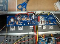
See picture attachment. I think this will tell you what is wrong. This resistor above R30 location and below the trimmer is reading 35.8VDC. Crazy high don't you think? But why and what to change out. Hopefully the trimmer is bad. And both board are reading about the same with same bias problems.
I did not use the schematic you are referencing as I could not print it out to be able to read it, so built with other schematic. Zoomed in on the drawing and can now see the "jumpers". Somewhere and I can't find it but thought it said in jumper locations small value resistors could be installed. Can't remember why either. Can't find build notes at this time.
Anyway with small value voltage drops in R30 and R6 would seem like "not a problem??" Have no idea. Will remove resistors and put in jumpers as schematic shows maybe tomorrow.
Thanks again for your ideas and help. Good thing the journey is as fun as the final completion.
Attachments
Your resistor above R30 is R5. It's normal to have 35+ volts across it.
Can you confirm the resistor values for R6 and R30?
Your R6 seems to be 562 ohm. If so, then the 1.86V across it means you only have
about 3.3mA going through your front end. This is far too low. You want
it to be about 8.4mA.
Can you try adjusting the LTP bias pot slowly until you get about 4.73V across
R6? Also then see if the dc offset changes and if you can trim it down with the
R7 trimmer?
Also please monitor the output stage bias current to make it doesn't get too high as you make
adjustments. (Trim it down as needed.)
Last edited:
- Home
- Amplifiers
- Pass Labs
- Aleph J illustrated build guide