
NOTE: this is a long shot... do it if you are keen on experimenting and you have time.
Connect the secondary windings to the power supply PCB, load the power supply PCB with amp PCB's, and then use a series combination of 0.1uF /50V AC film capacitor and a 20-ohm potentiometer (you'll need two sets of these), across each secondary winding. While the amp is ON (transformer fully loaded with both amp PCB's), rotate the potentiometers to see if the buzz changes... If you have an oscilloscope, monitor the AC windings for oscillations and see if you have any, and if you do, if the potentiometer rotation is affecting oscillations' amplitude.
Connect the secondary windings to the power supply PCB, load the power supply PCB with amp PCB's, and then use a series combination of 0.1uF /50V AC film capacitor and a 20-ohm potentiometer (you'll need two sets of these), across each secondary winding. While the amp is ON (transformer fully loaded with both amp PCB's), rotate the potentiometers to see if the buzz changes... If you have an oscilloscope, monitor the AC windings for oscillations and see if you have any, and if you do, if the potentiometer rotation is affecting oscillations' amplitude.
Bias issue
I finished assembly of my Aleph J, and am having an issue with the left channel bias. Right channel I was able to adjust offset and bias with no issue. however in the left channel, I can adjust offset to 0, but I cannot get the bias to go past .274 V. I have turned R27 to it's maximum and it will go no further.
I finished assembly of my Aleph J, and am having an issue with the left channel bias. Right channel I was able to adjust offset and bias with no issue. however in the left channel, I can adjust offset to 0, but I cannot get the bias to go past .274 V. I have turned R27 to it's maximum and it will go no further.
I spoke with Antek today. They want me to measure the temp of the transformer and rectifiers. They asked me to swap out rectifiers, if possible. I may have one extra one, but I’m not likely to have two. I also imagine that it is more likely that the transformer is problematic than the rectifiers. They also want me to swap out this transformer for the one I have in my M2x. I said no to the last point since Im not going to break anything that works well to test another that doesn’t. That’s not good engineering practice as I may end up with two amps with problems. I’ll go for the measurements and rectifiers and report back. Thanks
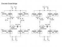
Best to isolate the problem. Take the transfo out, and put some load on the secondaries with resistors. Say if you have wired the diode bridge wrong, and a diode shorts half the cycle of the AC. Maybe you make the same error again when replacing the diodes or bridge. And you then make the wrong conclusion that the transfo is faulty.
(About temperature of the transfo, when connecting only the power supply without the amp's, the transfo must stay at about room temp.)
(About temperature of the transfo, when connecting only the power supply without the amp's, the transfo must stay at about room temp.)
To calculate load resistors use Ohm's Law. It works with AC voltage when the load is resistive (V = I x R).
The power rating of the resistors will need to be quite large though.
First to determine the load. You pointed out earlier that the transformer hummed with one channel connected. Each channel has two mosfets up and two mosfets down with the following current demand:
.40V across .47R for each mosfet
I=V/R= .40v/.47R = 0.85A per mosfet = 2 x 0.85A = 1.70A per V+ and V- per channel
Transformer secondary = 18VAC
Resistive load = V/I = 18VAC/1.70A = 10.6R
So the resistive load across each 18VAC secondary is 10.6R to approximate the load of one channel. Round up to standard resistor value.
Power requirement of the resistors P = IxIxR = 1.70A x 1.70A x 11R = 31.8W
As I mentioned at the beginning, the power handling requirement is quite high. You can series and parallel a bunch of 10W resistors to get say 60W at 11R. The resistors will get hot!
You will need a resistor load for each 18VAC secondary.
Or, swap out the rectifiers and also check temperature as suggested by Antek.
The 11R resistor loads are for one half amplifier load or one channel of the amplifier. You can perhaps try loading the transformer less (higher R value) to see if it hums if you do not have enough high wattage resistors.
tens of watts and tens of ohms starts to sound like an incandescent bulb to me.
Personally, it seems like you should be able to hookup your Aleph to your other transformer without too much dismantling.
Disconnect the +/-V & Ground wires from the aleph PSU to the problem Aleph channel and also disconnect the speaker output and unbolt the signal input. Unbolt the heatsink from the chassis that has the problem channel and bring it to your M2X enclosure. Remove the power leads going from your M2X PSU to Amp boards and then hookup your aleph amp still on the heatsink. Remove one channel of M2X speaker outputs and replace with aleph since you're using spades too, and you're all done. Can just let signal dongle.
If we're counting, you unhooked power between M2X PSU and Amp boards and 1 speaker output. In my mind that's very minor and extremely low risk of doing any damage and will give you the best answer if it's the transformer.
While this doesnt completely isolate the issue to the transformer, since there's still rectification and PSU board out of the test loop, I find it hard to believe those are causing any issue when one aleph amp channel is working and biasing up just fine.
Respectfully i don’t have a bad channel or if I do I don’t know which one it is. All I know is that I have a transformer that hums connected to either amp board of my AJ. The manufacturer is basically saying the problem is every part but theirs. I don’t want to take apart a working amp to test a bad one. That is the path to two not working amps. The only thing I can think of is connecting the secondaries of each amp to the other amp’s rectifiers (not at the same time) using a long wire and fastons. So basically powering the other amp with the first amp’s power inlet. Thoughts?
My mistake, I must have a couple of problems in the past handful of posts confused with each other.
I had considered mentioning your idea of longer secondary leads but wasnt sure about this potentially causing a ground loop issue and hum of its own.
The response from Antek is a little disappointing. One would have hoped they would send you a new one.
I had considered mentioning your idea of longer secondary leads but wasnt sure about this potentially causing a ground loop issue and hum of its own.
The response from Antek is a little disappointing. One would have hoped they would send you a new one.
So five wires between the two chassis: two for each of the two secondaries and one for the chassis ground. only power up the chassis with the transformer I’m testing? This would certainly rule out transformer noise (assuming I’ve thought through the procedure correctly) but would leave the rectifiers and the boards untested. Thanks
Quick question about transformers for 120v/60hz version of the Aleph J: from reading through this thread, I'm given to understand that any of these Antec transformers will do (yes, many are currently out of stock). Let me know if I'm missing something.
AS-3218 - 300VA 18V
AS-3220 - 300VA 20V
AS-4218 - 400VA 18V
AS-4220 - 400VA 20V
AN-5218 - 500VA 18V
AN-5220 - 500VA 20V
AS-3218 - 300VA 18V
AS-3220 - 300VA 20V
AS-4218 - 400VA 18V
AS-4220 - 400VA 20V
AN-5218 - 500VA 18V
AN-5220 - 500VA 20V
Respectfully i don’t have a bad channel or if I do I don’t know which one it is. All I know is that I have a transformer that hums connected to either amp board of my AJ. The manufacturer is basically saying the problem is every part but theirs. I don’t want to take apart a working amp to test a bad one. That is the path to two not working amps. The only thing I can think of is connecting the secondaries of each amp to the other amp’s rectifiers (not at the same time) using a long wire and fastons. So basically powering the other amp with the first amp’s power inlet. Thoughts?
I would get another transformer and install it. If same problem, you have two good transformers, which if you are like everyone else here you will end up using them in something.
If on the other hand it works, proving first transformer WAS defective, I would send it back to them and demand refund, posting outcome here. This site has sent them business for sure, maybe they don't need it or can get by without our business, but there are other manufacturers of transformers.
On the other hand, defective units are rare, but when they happen they need to take responsibility. That said I'm sure they get all sorts of DIY folks who have made some mistake.
If a replacement works, they need to re evaluate and refund. Keep all advised of what happens.
Russellc
- Home
- Amplifiers
- Pass Labs
- Aleph J illustrated build guide