Short the inputs and see if you still have hum. I suspect you will. An input transformer wouldn’t help that.
Very true. Please test this first.
Short the inputs and see if you still have hum. I suspect you will. An input transformer wouldn’t help that.
How exactly do I short the inputs while checking for hum?
Do I disconnect the preamp, leave the amp connected to the speakers and then short across the positive and negative of each input in the amp? I’m a little nervous about doing that.
Marantzfan - please post a bunch of well-lit, in-focus photos. We’ll start looking.")
Will do.
How exactly do I short the inputs while checking for hum?
Do I disconnect the preamp, leave the amp connected to the speakers and then short across the positive and negative of each input in the amp? I’m a little nervous about doing that.
Turn off the amp first. Connect both positive and negative input to the ground. Turn on the amp, and see you can still hear the hum. If you're worried, disconnect the speaker, and check AC and DC voltage of the speaker output.
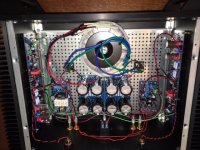
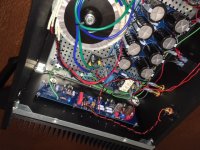
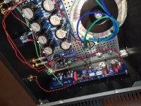
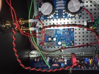
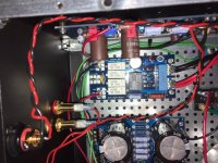
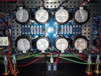
Here are some pictures. Hopefully I did something really obvious and easy to correct.
Attachments
Last edited:
You could consider installing a Quencharc or a PMR210 (both sold by Mouser) to lengthen the lifetime of your power switch. Me personally, I favor the second circuit topology (across-the-load) rather than the first (across-the-contacts). Why? Displacement current.
_
Would you recommend that this be used instead of the .0033uf line cap in the standard Pass power supply or in addition to that cap? Just curious on your findings.
Turn off the amp first. Connect both positive and negative input to the ground. Turn on the amp, and see you can still hear the hum. If you're worried, disconnect the speaker, and check AC and DC voltage of the speaker output.
So, I could accomplish this by connecting an alligator clip to the positive on each input and connecting the other end of the alligator clip to ground?
Same with the negative of each input?
So, I could accomplish this by connecting an alligator clip to the positive on each input and connecting the other end of the alligator clip to ground?
Same with the negative of each input?
Yes. You don't have to check your life insurance policy before doing it.
Yes. You don't have to check your life insurance policy before doing it.
Great! That was my next question.
Your negative inputs should be already connected to the ground for unbalanced connection, anyway.
Yes, I did install the jumper on the amp boards between the negative out and ground.
So with that said, can I just attach alligator clips across the positive and negative of each input?
Yes, I did install the jumper on the amp boards between the negative out and ground.
So with that said, can I just attach alligator clips across the positive and negative of each input?
Yes. Connect positive inputs to the ground.
Here are some pictures. Hopefully I did something really obvious and easy to correct.
Looking at the pictures, I don't see a ground lift in the power supply ground to chassis ground. Use either a thermistor as in the FW supplies or bridge/diodes.
Another thing to do is always twist wires together with their returns. For instance I see that your positive and negative supply wires are twisted together but the ground return wire is free. The ground wire should be twisted together with the positive and negative wires from power supply to boards.
Likewise I see that the speaker ground wire is not twisted with the signal wire for its entirety. Twist the two wires together all the way to the speaker protection board and then twist together to the speaker jacks.
Another item is the location of the ground connection to the PS board. It is best to join the positive and negative supply grounds and take the ground wire from the board at exactly the midway point between the negative and positive grounds.
Once all that is done, try rotating the power transformer. Usually there is one position where the noise caused by radiation from the transformer is minimized.
A good read on minimizing amplifier hum and noise is by diyAudio member Bonsai:
http://hifisonix.com/wordpress/wp-content/uploads/2019/02/Ground-Loops.pdf
It is rather long but you can skip to the end where he summarizes and shows practical information/tips.
Short the inputs and see if you still have hum. I suspect you will. An input transformer wouldn’t help that.
Ok, just did this and with the inputs shorted there is no hum. So, what does this mean?
Looking at the pictures, I don't see a ground lift in the power supply ground to chassis ground. Use either a thermistor as in the FW supplies or bridge/diodes.
Just to verify, even if I am using the soft start board, I will still want to install a thermistor inline between the PSU board ground and the STR ground?
Another thing to do is always twist wires together with their returns. For instance I see that your positive and negative supply wires are twisted together but the ground return wire is free. The ground wire should be twisted together with the positive and negative wires from power supply to boards.
Are you referring to the V+, V- and GRND from each amp board to the PSU board? I don't have any of those twisted together.
Likewise I see that the speaker ground wire is not twisted with the signal wire for its entirety. Twist the two wires together all the way to the speaker protection board and then twist together to the speaker jacks.
Ok. There is maybe an inch on one end and a half an inch on the other just before these wires meet either the board or the jacks. I can certainly add a few more twists at each end if you think it will make a difference.
Another item is the location of the ground connection to the PS board. It is best to join the positive and negative supply grounds and take the ground wire from the board at exactly the midway point between the negative and positive grounds.
This I don't follow. There are two banks where you can connect ground to the PSU. One is on the V+ board and one is on the V- board. With that said, I did install several jumpers to connect the two boards.
Once all that is done, try rotating the power transformer. Usually there is one position where the noise caused by radiation from the transformer is minimized.
This is something I haven't tried. Is there a certain orientation that tends to work best?
You have a ground loop.
Does anything in the photos I posted jump out as an obvious cause for a ground loop?
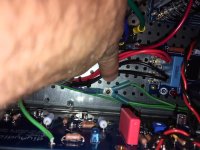
BTW, the STR ground junction in the last picture is linked to the purple transformer wire, the IEC inlet ground and finally to one of the ground terminals on the PSU board.
- Home
- Amplifiers
- Pass Labs
- Aleph J illustrated build guide