An excellent question.
I separate the audio ground from the chassis ground with a 10 Ohm resistor for each channel. The resistors are protected with back-to-back diodes to limit the current they have to carry in the event of a circuit fault of some sort. The easy way to do this is with a monolithic bridge rectifier, as written by N. Pass in his Zen V4 article. Another way to do this is with CL-60 NTC thermistors which have a cold resistance of 10 Ohms. No protection diodes are necessary with the thermistors.
The other thing I have done with both the Aleph J and my M2x is wire the speaker negative terminals directly to the ground(s) of the PSU board(s). Seems to work very well.
Thanks for the answer.
I'm not a fan of putting secundairy ground to earth otherwise when it is for protection or if you use a switching power supply which used a lot of emi/rfi.
I think best way is chassis to earth for safety reason and wire all secundairy grounds (0) at one point (floating design).
The thermistor is a nice option, didn't know that.
Well, I've got hum in both channels and turn off thump. Didn't get to music yet, sadly.
My first thought was grounding for the hum. Input and output wires are all twisted pairs and run as far from other wiring as possible.
I have a star ground on the chassis, where the IEC inlet ground, PSU board ground and purple transformer (Antek) wire are all joined.
Also, I have the soft start and speaker relay boards installed. Speaker relay board is running off the 24V from the PSU board. Figured with the relay board there wouldn't be a turn off thump...
Any ideas on where to start?
Remove the soft start and speaker relay boards before doing anything else. Hook up the PSU and channel board outputs as N. Pass intended. Maybe save the soft start and relay boards for some dodgy A/B amp, but not a Papa amp.
Interesting.
Is the thinking that these two "add ons" are whats causing the two issues? Also, if I remove the soft start, don't I still need some type on in-rush protection? I have some CL-60 Thermistors left over from my F5 build. Do I just wire one into the mains in somewhere?
Those two add-ons are unnecessary to begin with and will complicate your debug process. There are too many ways to hook up those boards in a way which will cause hum.
As I mentioned above, the Aleph J already has a current limiting feature. Also, since you are using a fairly standard power supply with a normal amount of capacitance, more elaborate soft-start mechanisms are unnecessary. For N. American household voltage, the two primaries of your power transformer are wired in parallel. A simple NTC thermistor in series with each of those primaries is a sufficient soft-start. I prefer using the CL-70 thermistors, but the CL-60 work fine since you already have those. Follow the build guides for how to wire the primary side of your transformer with the thermistors in place.
Finally, read my recommendations above for how to connect the audio ground to the chassis ground. (Hint: use another CL-60) The only things that should be connected to the chassis ground are the AC power safety ground wire, the transformer shield wire, and a single connection to audio ground.
Those two add-ons are unnecessary to begin with and will complicate your debug process. There are too many ways to hook up those boards in a way which will cause hum.
Fair enough, I will remove them both. Hopefully, there in was the root of my hum and/or turn off thump problem.
As I mentioned above, the Aleph J already has a current limiting feature. Also, since you are using a fairly standard power supply with a normal amount of capacitance, more elaborate soft-start mechanisms are unnecessary. For N. American household voltage, the two primaries of your power transformer are wired in parallel. A simple NTC thermistor in series with each of those primaries is a sufficient soft-start. I prefer using the CL-70 thermistors, but the CL-60 work fine since you already have those. Follow the build guides for how to wire the primary side of your transformer with the thermistors in place.
Finally, read my recommendations above for how to connect the audio ground to the chassis ground. (Hint: use another CL-60) The only things that should be connected to the chassis ground are the AC power safety ground wire, the transformer shield wire, and a single connection to audio ground.
Will do, and coincidentally, I just so happen to have 3 CL-60's on hand, so I'll be able to get this done quickly. Not tonight unfortunately, because I have to go to a social thing... but certainly over the weekend.
While I'm doing this, is there anything else that I might want to look at while I've got it on the bench again?
BTW, thank you so much for your help!
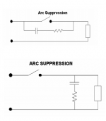
You could consider installing a Quencharc or a PMR210 (both sold by Mouser) to lengthen the lifetime of your power switch. Me personally, I favor the second circuit topology (across-the-load) rather than the first (across-the-contacts). Why? Displacement current.
_
_
Attachments
Oh dear.. Advice needed.. Bad hum and ~4V across the output terminals on one channel..
Status: First time playing music today. All has been going well until today. Both channels were setup with 0V on the output terminals, 400mV bias. Nice and stable for hours. Today when I turned it on it blew a 1.25A fuse. Then another.. So I’ve put in a 1.5A fuse. All good, no more blown fuses. Connected to speakers and DAC for first time. Bad hum on left side but plays music still. Rechecked voltages.. The side with hum now has about 4V across the output... Bias still around 400mV. Any suggestions what I’ve done?
Status: First time playing music today. All has been going well until today. Both channels were setup with 0V on the output terminals, 400mV bias. Nice and stable for hours. Today when I turned it on it blew a 1.25A fuse. Then another.. So I’ve put in a 1.5A fuse. All good, no more blown fuses. Connected to speakers and DAC for first time. Bad hum on left side but plays music still. Rechecked voltages.. The side with hum now has about 4V across the output... Bias still around 400mV. Any suggestions what I’ve done?
An excellent question.
I separate the audio ground from the chassis ground with a 10 Ohm resistor for each channel. The resistors are protected with back-to-back diodes to limit the current they have to carry in the event of a circuit fault of some sort. The easy way to do this is with a monolithic bridge rectifier, as written by N. Pass in his Zen V4 article.
Is that something like this?
Earthing (Grounding) Your Hi-Fi - Tricks and Techniques
Oh dear.. Advice needed.. Bad hum and ~4V across the output terminals on one channel..
Status: First time playing music today. All has been going well until today. Both channels were setup with 0V on the output terminals, 400mV bias. Nice and stable for hours. Today when I turned it on it blew a 1.25A fuse. Then another.. So I’ve put in a 1.5A fuse. All good, no more blown fuses. Connected to speakers and DAC for first time. Bad hum on left side but plays music still. Rechecked voltages.. The side with hum now has about 4V across the output... Bias still around 400mV. Any suggestions what I’ve done?
Unfortunate news. Sorry to hear.
My unit pulls (according to the wall plug power meter) around 1.15-1.20 A at the wall, so I opted for a 1.5 A fuse also and haven't had an issue. I see a rise to ca. 1.6 A at start up but that's a short transient and the slow blow feature avoids a problem.
I'd expect that there'll be a call from those who can offer serious assistance for photos.
Having one functional channel at least gives you a reference point to compare against.
Remove the soft start and speaker relay boards before doing anything else. Hook up the PSU and channel board outputs as N. Pass intended. Maybe save the soft start and relay boards for some dodgy A/B amp, but not a Papa amp.
Interesting.
Is the thinking that these two "add ons" are whats causing the two issues? Also, if I remove the soft start, don't I still need some type on in-rush protection? I have some CL-60 Thermistors left over from my F5 build. Do I just wire one into the mains in somewhere?
Those two add-ons are unnecessary to begin with and will complicate your debug process. There are too many ways to hook up those boards in a way which will cause hum.
As I mentioned above, the Aleph J already has a current limiting feature.
If I was debugging, I'd simplify too to eliminate potential issues.
That said, I've built up and installed the store's soft start / speaker protection combo with a single transformer with dual secondaries. I chose not to install the NTC on the primary side of the tansformer. Touch wood, it's been a case of "nothing much to write home about" for the process of going hot, setting up offset and bias and then going on to play back audio. My first build connecting to mains AC.
Maybe one for the YMMV stakes?
")
One quick question. I see a lot of folks using a twisted pair of CAT-5 for input wiring. I used some neotech 18g hookup wire, that I twisted together.
Could my choice of wire used in any way be contributing to the hum?
Also, for reference. My speakers are Altec 604-8g which are 100db and the preamplifier I’m using is a Bottlehead BeePre.
Could my choice of wire used in any way be contributing to the hum?
Also, for reference. My speakers are Altec 604-8g which are 100db and the preamplifier I’m using is a Bottlehead BeePre.
If I was debugging, I'd simplify too to eliminate potential issues.
That said, I've built up and installed the store's soft start / speaker protection combo with a single transformer with dual secondaries. I chose not to install the NTC on the primary side of the tansformer. Touch wood, it's been a case of "nothing much to write home about" for the process of going hot, setting up offset and bias and then going on to play back audio. My first build connecting to mains AC.
Maybe one for the YMMV stakes?
I looked at your pictures and can’t gifure out what I’ve dine differently that is causing the hum... other than the location of where I mounted both boards.
One quick question. I see a lot of folks using a twisted pair of CAT-5 for input wiring. I used some neotech 18g hookup wire, that I twisted together.
Could my choice of wire used in any way be contributing to the hum?
Also, for reference. My speakers are Altec 604-8g which are 100db and the preamplifier I’m using is a Bottlehead BeePre.
For my unit, the power and speaker cabling were installed to this spec:
- 32 strand, 17AWG heavy duty, high current tinned copper wire with a PVC insulator suitable for indoor 240V and heavy duty wiring.
- Size: 1 x 32/0.20
- Voltage Rating: 300V AC
- Current Rating: 10 Amps
- Outside Diameter: 2.55mm
- Conductor Area: 1.01mm2
- Conductor Gauge: 17AWG
- Temperature Rating: 90°C
https://media.digikey.com/pdf/Data Sheets/CNC Tech PDFs/1569-20-1-0500-0xx-1-TS.pdf
Nothing flash but it's working fine so far. Just made sure that I gave pairs a bit of a twist and if I had 3 cables, then I gave them a plait. From the link about twisted pairs, there's coverage of CAT cable that mentions that its shielded. That could provide some advantage but from reading that piece, twisting should get you most of the way there.
Note that for my build I've not hooked it up for SE inputs. Inputs are XLR so that I get the advantage of balanced circuit architecture. I also ensured that there is a star earth/ground. The transformer is placed smack in the middle of the chassis and riser panels have been used that provide some shielding between the transformer and the PCBs. There's also a ground loop breaker installed along the lines of the discussion above from TungstenAudio. Plus, the transformer has a GOSS band and electrostatic shielding. I've also tried to route cabling so that there is reasonable separation between different wiring runs.
I was probably being overly cautious but I'd had some hum hassles in my home system prior, so I applied a plan of once bitten twice shy prevention.
Post some photos of your Aleph's insides and you'll probably get some useful suggestions from eyes with helpful experience behind them. All the best and hope you get sorted soon ..

My solution would be adding Cinemag 600 ohm transformer. Somewhat cheating, but balanced input would solve all the hum issue + AJ will sound better!
Are you referring to adding the cinemag to the BeePre or the Aleph J?
Are you referring to adding the cinemag to the BeePre or the Aleph J?
Output transformer is less expensive and should work fine.
Another benefit having transformer is you can remove input cap from AJ.- Home
- Amplifiers
- Pass Labs
- Aleph J illustrated build guide