Only with enough quantity of parts ")
The GR is at $2 a piece for the time being. One possible "alternative" is to buy enough GR to match them in pairs to make the BL, like 2 x 3.5mA GR's in parallel => one BL at 7.XX mA at $4, not too bad. The remaining unmatched GR's ain't waste either.
I am going to order some and will report how the above scheme plays out
Not that expensive, listed in HK dollars. Last I bought were less than what store asks...May be price has gone up?Alwieit is the Israel fellow, his are real, but yes, I believe he is out of BL as well. <snip>
Russellc
Last edited:
Totally understood. I am hoping some will land in the 6mA range, then they can mate to my low idss 2SK170BL without the penalty. Only a few of my limited 2SJ74BL's are in this low idss range, so I have quite a few 2SK170BL's that are in this range with partner.
To me it is worth a try as long as the jfet's are real which always beat the fakes regardless. It is a gamble afterall.
Edit: For the purpose of AJ, as long as the IDSS is above 5mA, I believe they can be used. The CCS in the tail pumps about 10mA.
To me it is worth a try as long as the jfet's are real which always beat the fakes regardless. It is a gamble afterall.
Edit: For the purpose of AJ, as long as the IDSS is above 5mA, I believe they can be used. The CCS in the tail pumps about 10mA.
Last edited:
Also almost double Yfs. When applied in Aleph J would extend top end similar to the J2?. . . . In doing so you also doubled the capacitances.
. . . .
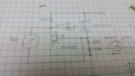
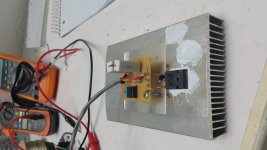
I built a jig for matching the IRFP240 MOSFETS. I simply used the constant current source circuit from the amplifier and measured the voltage across the Gate and Source. I ran the power supply on a Variac and monitored the VGS for about 5 minutes and wrote the VGS on the FET. Out of 24 FETs I came up with 8 pairs all matched within 2 or 3 mv of each other. It may be time consuming but it works well. I am thinking that a larger heatsink with a large power supply could do multiple fets as all the drain leads could be common. No insulators would be needed.
Attachments
Pass DIY Addict
Joined 2000
Paid Member
If you order in multiples of 25 (a full tube), you're very likely to get lots of matched pairs/quads/etc. I matched mine with a similar jig, but without the heatsink - they were just in free air. I used 20v, 0.75A for about 45 seconds - any more and they get too hot to handle. This was enough time to obtain closely matched pairs for my big Aleph-X amps. For these mosfets, most people want to match them at the specific voltage and bias that they'll see in the completed amp, but it seems that simply matching them at any realistic voltage and bias level will provide good results for other voltages and bias levels as well.
I did notice a change in VGS as the FET heated up on the jig. The goal was to take all the FETS to be matched safely to the same temperature they would see in the amplifier. As I was in no hurry I found 5 minutes worked just fine. I did have two different batches so my yeild was lower than if they had been from the same lot. After mounting the FETS to the Heatsink, I checked the resistance between all the Drain leads of the Fets to chassis ground.
Pass DIY Addict
Joined 2000
Paid Member
Yep, they do change as they heat up for sure!
But, once you find ones that track one another at the same rate for some fixed voltage level, they also seem to follow one another for other voltages and currents as well. Thus, matching at ANY reasonable voltage and current is sufficient. I've matched over a hundred mosfets for various amps and haven't found any that don't follow this rule.
Once they match - they are a match!
Hey Everybody,
I hope this is the right thread to post this in. If not please let me know.
After building the Amp Camp monoblocks, an F5, a Sony VFET DIY, I have just finished the right channel for an Aleph J. Everything seemed go smoothly and it sounds great. I have the bias at 400mVdc and DC offset adjusted to zero. Temp on my heatsink after one hour hovers at about 42-43°C.
That said there are a few things that happened along the way that seemed a little odd to me:
1. Before powering up I double checked the board and the components to make sure I got them all in the right place. I had set the R27 pot to 68k ohms per the Illustrated build guide—thanks 6L6!— before soldering but once soldered in I double checked it with the handy pads on each side of the pot. When I first put the probes on the resistance was very low but then it started slowly climbing and after about 20 sec or so leveled off and stopped at 68k. This may be normal but I hadn’t seen it before.
2. When I first powered the Aleph J board on the bias, with R27 set at 68k, was quite high, around 650mVdc. I had to turn the multi-turn pot quite a few turns to get it down to 350mV. Right now when I measure the R27 pot resistance on the board it’s at about 16k. Does that sound right?
2. I always start new circuits for the first time with a dim bulb setup, 100 watt. Usually for a split second the bulb glows very bright and then gets really dim, almost out. However, when I first powered up the Aleph J, as usual, it got really bright for the spilt second and then got dimmer but not as dim as on my other projects, probably about 2/3 as bright. I biased it to around 350 mV, kept an eye on the temp, left it for 30mn then biased to 400mVdc and set the dc offset to zero. I did all this with the input shorted. Then tried some music with an old speaker and it sounded fine.
3. When I turned the amp off after an hour the PSU red, positive LED went dim right away while the green, negative rail one stayed quite bright for several minutes. I disconnected the Alpha J board and turned the unloaded PSU on and off again. Both LEDs stayed lit for several minutes. Kind of strange.
4. When I turn the amp off there’s a slight" fa-thump". From several posts here it looks like this is normal with the Aleph J and actually I have more of a turn-off thump with my AC monoblocks. Neither my F5 nor VFET has turn-on or turn-off noise though. However, the turn-off noise worries me just a bit because I first noticed it when I did something I normally don’t do: turn the amp off before turning the music off and turning the volume down. When I did that I was surprised by this sort of crackling “squEEEALch”. Tired it again with the music turned off, so no signal, and got the more familiar low “fa-thump”. BTW, my ACA’s have a louder one syllable "THUMP” but the Aleph J is definitely a two syllable “fa” then “thump” but a lot softer than the ACA’s. I tried powering down by using a power strip instead of the PEM switch but the noise was still there. If I don’t that with the ACA’s there’s no thump.
I kind of think all these things might have the same origin.
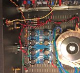
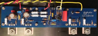
I am attaching a photos of the PSU and the Aleph J PCB . I took the PSU photo after I had disconnected the rails from the Aleph J board. In the meantime I'm building the left channel board so it might be interesting to see if the same thing happens or not.
I would be very appreciative for any advice. And, as always, thanks to Mr Pass, Diyaudio.com, 6L6 and all you guys for making this all possible.
Dan
I hope this is the right thread to post this in. If not please let me know.
After building the Amp Camp monoblocks, an F5, a Sony VFET DIY, I have just finished the right channel for an Aleph J. Everything seemed go smoothly and it sounds great. I have the bias at 400mVdc and DC offset adjusted to zero. Temp on my heatsink after one hour hovers at about 42-43°C.
That said there are a few things that happened along the way that seemed a little odd to me:
1. Before powering up I double checked the board and the components to make sure I got them all in the right place. I had set the R27 pot to 68k ohms per the Illustrated build guide—thanks 6L6!— before soldering but once soldered in I double checked it with the handy pads on each side of the pot. When I first put the probes on the resistance was very low but then it started slowly climbing and after about 20 sec or so leveled off and stopped at 68k. This may be normal but I hadn’t seen it before.
2. When I first powered the Aleph J board on the bias, with R27 set at 68k, was quite high, around 650mVdc. I had to turn the multi-turn pot quite a few turns to get it down to 350mV. Right now when I measure the R27 pot resistance on the board it’s at about 16k. Does that sound right?
2. I always start new circuits for the first time with a dim bulb setup, 100 watt. Usually for a split second the bulb glows very bright and then gets really dim, almost out. However, when I first powered up the Aleph J, as usual, it got really bright for the spilt second and then got dimmer but not as dim as on my other projects, probably about 2/3 as bright. I biased it to around 350 mV, kept an eye on the temp, left it for 30mn then biased to 400mVdc and set the dc offset to zero. I did all this with the input shorted. Then tried some music with an old speaker and it sounded fine.
3. When I turned the amp off after an hour the PSU red, positive LED went dim right away while the green, negative rail one stayed quite bright for several minutes. I disconnected the Alpha J board and turned the unloaded PSU on and off again. Both LEDs stayed lit for several minutes. Kind of strange.
4. When I turn the amp off there’s a slight" fa-thump". From several posts here it looks like this is normal with the Aleph J and actually I have more of a turn-off thump with my AC monoblocks. Neither my F5 nor VFET has turn-on or turn-off noise though. However, the turn-off noise worries me just a bit because I first noticed it when I did something I normally don’t do: turn the amp off before turning the music off and turning the volume down. When I did that I was surprised by this sort of crackling “squEEEALch”. Tired it again with the music turned off, so no signal, and got the more familiar low “fa-thump”. BTW, my ACA’s have a louder one syllable "THUMP” but the Aleph J is definitely a two syllable “fa” then “thump” but a lot softer than the ACA’s. I tried powering down by using a power strip instead of the PEM switch but the noise was still there. If I don’t that with the ACA’s there’s no thump.
I kind of think all these things might have the same origin.
I am attaching a photos of the PSU and the Aleph J PCB . I took the PSU photo after I had disconnected the rails from the Aleph J board. In the meantime I'm building the left channel board so it might be interesting to see if the same thing happens or not.
I would be very appreciative for any advice. And, as always, thanks to Mr Pass, Diyaudio.com, 6L6 and all you guys for making this all possible.
Dan
Attachments
1) Bias is not just a function of the pot, it’s the pot and the Vgs of the particular mosfets you have. It’s going to vary, hence why its a pot.
2) see No.1
2 a ) Alephs pull a lot of current. They get hot. Hence the bulb staying a bit lit after the inrush.
3) The circuit discharges the positive rail a lot faster than the negative. That’s normal for this amp
4) See no.3
2) see No.1
2 a ) Alephs pull a lot of current. They get hot. Hence the bulb staying a bit lit after the inrush.
3) The circuit discharges the positive rail a lot faster than the negative. That’s normal for this amp
4) See no.3
I brought my J on a Variac and turned the bias pot down as I brought the line voltage up, and as you experienced I turned quite a few turns. I used the Diy speaker protector and now my amp is tump-less. This is a really really nice sounding amp. Well worth the trouble to build.
Hi Eslheadphone,
Thanks for the info. I actually have a speaker protection board I’ll add once I get both channels done. The turn off thump really isn’t very loud at all; I’d just never run into things like the rails discharging like that before. I was relieved to find out that’s normal.
Thanks,
Dan
Thanks for the info. I actually have a speaker protection board I’ll add once I get both channels done. The turn off thump really isn’t very loud at all; I’d just never run into things like the rails discharging like that before. I was relieved to find out that’s normal.
Thanks,
Dan
what a wonderful guide/tutorial!
this is a wonderful guide/tutorial!
the bottom line - how much does building this amp cost?
thanks.
An illustrated guide to building the Aleph J
This is a guide to building the Nelson Pass / Firstwatt 'Aleph J' amplifier.
You are free to comment or question.
this is a wonderful guide/tutorial!
the bottom line - how much does building this amp cost?
thanks.
$700 give or take, depending on how much you have laying around and/or can scrounge or fabricate.
If you buy all the stuff available from the diyAudio store and all fresh parts from Mouser or Digi-Key I bet you can be pretty close to $700, maybe a tad under.
thanks. is it worth the $700?
- Home
- Amplifiers
- Pass Labs
- Aleph J illustrated build guide