Q: Can it have anything to do with the fact that the volume control and the source switch are mounted on a steel plate so it is that one that has to be grounded....??
......if you lay your hand on this steel plate, does the humming change? (better or worse?)
The steel plate is already connected to ground so that is not it either the problem. Tnx for the thought.
If I now don't get it right then the other solution is to apply a potentiometer/attenuator that I know is working so then my question is, do I think right when I want to apply this way, showing only one channel??

And if the thought descriebed in the picture is correct that mean that I need to use a 4-gang potentiometer/attentuator to get both channels right and left, balanced all way to the output, or....??
I hope I am getting this right cause I am not shure but logic is saying yes.
Finished
Ok I have finished it (for the moment)!!
Sound is very good and refined but I have just a small issue buggering me.
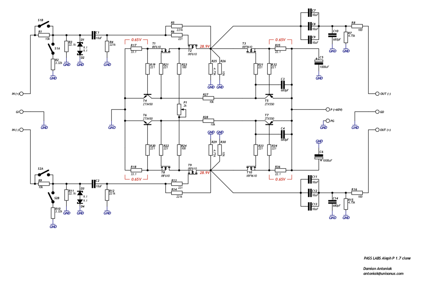
When I try to set the trimpots it is no problem getting the two channels within 1 or 2 mV AC of each other but when I set them I have about 640 mV over the 22R resistors and I can't get it down.
I saw earlier in the thread that 400-450 mV was to aim for but I can't get them there.
Then there is another thing I am wondering about. I have from my DAC appr. 1.850 V AC in to the preamp when playing a 1000 Hz testtone but the signal out from the preamp is only about 1.650 V AC out from the preamp, shouldn't I get some more gain??
If I try to go higher on the trimpots then I also raise the voltage over the 22R resister slightly going up to about 650 mV.
Anyone who have any idea??
Ok I have finished it (for the moment)!!
Sound is very good and refined but I have just a small issue buggering me.
When I try to set the trimpots it is no problem getting the two channels within 1 or 2 mV AC of each other but when I set them I have about 640 mV over the 22R resistors and I can't get it down.
I saw earlier in the thread that 400-450 mV was to aim for but I can't get them there.
Then there is another thing I am wondering about. I have from my DAC appr. 1.850 V AC in to the preamp when playing a 1000 Hz testtone but the signal out from the preamp is only about 1.650 V AC out from the preamp, shouldn't I get some more gain??
If I try to go higher on the trimpots then I also raise the voltage over the 22R resister slightly going up to about 650 mV.
Anyone who have any idea??
Last edited:
sorry , which one is ref. schematic ?
Original om Kojas board
Hello to diyaudio comunity. I build bosoz preamp and I don't know where to put volume
Ive just build the Joshua tree stepped attenuator by pear tree audio. Its one of them newfangled relay based attenuators. I believe it has a roughly fixed output impedence. Im hoping its well suited to this build. Im pretty ignorant about this new hobby of mine! What did you use?
Need veteran PCB part list ...
Attachments
Need veteran PCB part list ...
Wait.....?! this is veterans board right?
Attachments

yeah .....
nothing really to set , except little tweak of P1 , to equalize gain between channels
volume pot originally at output
SM attached

Zen your picture was gone
boredom to look for bucket pics
anyway , 2K trimpot is definitelly for gain tweaking , while (by value) 50R trimpots are definitely for fine tuning of Iq , left and right side
take proper pictures of trimpot area , so we can see few resistors around, to give you some guidelines how to set it
any other text info , besides Pass P1.7 ?
vol pot - same as in original schematic , on output
I would use 4k7 log pot there ........ 10K max.
Dear ZM
Where we put vr2 & vr3
Hope this work
Rgds
Hi folks
Just a heads up. I powered up my boards and did some basic DC checks. The basics looked Ok. I shorted one input to ground and hooked up my signal generator. It seemed to be working but I had a large imbalance (10%) in the +and_ outputs. The 20ma current sources also seemed to be imbalanced.
I had to leave it until I got home tonight. I had a suspicion that the circuit could be oscillating. Sure enough, I got out the scope and found the output had RF riding on the 1khz sine wave. The oscillation frequency was about 8mhz. It was more on one phase then the other, depending on which input was grounded. I found that the 20ma current sources Q12 and Q14 were oscillating. The Fets and transistors both have stopper resistors of 221 ohms. I took a second 221 ohm resistor and placed it in parallel with these resistors. Lowering the value of the gate stopper caused the oscillation to stop while lowering the base stopper resistor caused the oscillations to increase. It seemed counter intuitive to lower the gate stopper so I replaced the base resistors R52 and R67 with 499ohms and the problem was fixed. I now have a balance within .01volts with an output of 10volts on each phase.
If anyone experiences a similar imbalance it should be a symptom of an oscillation. A scope is very handy to have for situations like this!
Hi Bfpca,
You may remember I have Aleph P1.7 that a friend of mine built with KK boards. I was having trouble with the Dantimax RelVol3 (distortion when changing volume). Since then I have moved to Australia and all my gear was packed up for qute a while.
I had given up on the Dantimax problem and a DIY Audio member gave me an Aleph P1.7 board with integrated volume control (looks the same as SE MOSFET full balanced +128 step volume control PCB ! | eBay ) that he was not using. I populated the board and used my own design arduino based board to control the volume relays on the board as well as control input selection I designed.
I just completed the preamp and after initial testing hooked it up single ended to a Squeezebox Classic as source and a diy F4 with some old speakers. It sounds OK as far as I can judge using these speakers
")
After re-reading your post I checked the amp using ARTA, REW and DiaNa and an old M-Audio Audiophile USB soundcard (never used them before so not sure if I am measuring things correctly) and noticed I had different distortion patterns on the + and - part of the amp on the channel I tested.
I have a Rigol scope (again, hardly any mileage and still working out how to use it) and was wondering what to look for (and how!) to see if I may also have the osciallation problem you mentioned.
Thanks,
Albert
I figured out what was happening with the attenuator relay switching noise. I had the same issue when I built a hand wired logic controlled output attenuator. When you are switching from one volume level to another several relays can be switching at one time. The output impedance is high due to the current source output. During the relay switching period all the relays can sometimes be open circuit and the full unattenuated output goes out of the preamp. In other words, big noises at certain volume control transitions. There are ways to deal with this and I tried a few but because I was not using Arduino but 4000 and 7400 series gates to do the logic it was very difficult to make changes. While I was dealing with this problem I discovered some more serious oscillations a higher output levels. Everything would be fine until a certain level and then a large oscillation that is easy to see on the scope would occur.Hi Bfpca,
You may remember I have Aleph P1.7 that a friend of mine built with KK boards. I was having trouble with the Dantimax RelVol3 (distortion when changing volume). Since then I have moved to Australia and all my gear was packed up for qute a while.
I had given up on the Dantimax problem and a DIY Audio member gave me an Aleph P1.7 board with integrated volume control (looks the same as SE MOSFET full balanced +128 step volume control PCB ! | eBay ) that he was not using. I populated the board and used my own design arduino based board to control the volume relays on the board as well as control input selection I designed.
I just completed the preamp and after initial testing hooked it up single ended to a Squeezebox Classic as source and a diy F4 with some old speakers. It sounds OK as far as I can judge using these speakers
After re-reading your post I checked the amp using ARTA, REW and DiaNa and an old M-Audio Audiophile USB soundcard (never used them before so not sure if I am measuring things correctly) and noticed I had different distortion patterns on the + and - part of the amp on the channel I tested.
I have a Rigol scope (again, hardly any mileage and still working out how to use it) and was wondering what to look for (and how!) to see if I may also have the osciallation problem you mentioned.
Thanks,
Albert
At that point I packed it in on the Aleph P. I could not invest any more time on it.The oscillations may be caused by the board layout, the parts used, temperature related, my particular chassis layout, etc. If I had used an Arduino based attenuator solution then I would have been much better off when it came to making changes.
If you look at the unattenuated output of the preamp and feed it a large sinewave ( the level of most sources which could be as much as 4v rms) you should easily be able to see if you have the same issues. Make sure it is up to full temperature. Hopefully you do not find the same issues.
Brian
Last edited:
Thanks for your reply Brian. I will try to find the source of my trouble. I assume I should see identical (or close to identical) FFT graphs on + and - of the outputs? I noticed amongst other things that the 2nd/3rd ratio is not the same. This does not seem normal to me.
How do you see a high frequency oscillation? I assume the scope will use the primary (say 1 kHz) signal as trigger and display it.
Thanks,
Albert
Scope-noob
How do you see a high frequency oscillation? I assume the scope will use the primary (say 1 kHz) signal as trigger and display it.
Thanks,
Albert
Scope-noob
Hi Albert,
when I look for oscillation using my Rigol scope, I display the signal from the signal generator (the 1 kHz going into the amp / pre-amp under consideration) on one channel, and the output of the amp on the second channel.
The first channel (input) should show a clean, sharp 1 kHz sine wave.
Ideally, the second channel (amp output) also shows a clean sine wave of higher amplitude.
If you have oscillation, one hint would be that the sine wave of the amp output would look hashy (not a thin line, but broad).
You can also see it on a 1kHz rectangle, where the horizontal top / bottom of the amp output looks like painted with a broader brush ...
You can the go searching for the oscillation frequency by triggering on the second channel (amp output), and switching the time base to higher and higher frequencies. In my case, the amp under consideration (a Sony V-FET 4650) oscillated (even with inputs grounded) at about 6 MHz with a nice sine wave of around 150 mV rms amplitude ...
Successful measuring,
best regards,
Claas
- Home
- Amplifiers
- Pass Labs
- Pass Aleph P 1.7 preamp builders thread