Im stuck... Just ran into a problem just as i was finishing my aleph p..
My regulated power supply has gone wonky. Im using veterans boards. One power supply board produces about 60volts dc and the other about 90 dc.
They both worked fine last i tested them. There was a small scent of burning and the fuse blew because i had accidentally reverse polarities to the boards and control circuit.
What might have happened to my power supply boards to make them produce those weird voltages. The voltage is fin after the rectifiers and caps, but wrong at the output after the zener diodes etc...
Help?
If i remember correctly, its supposed to be 60 or 80 v or something each
At a guess I'd say the zener reference is kaput. That'd leave you with no voltage reference on the gate of the mosfet and your output would be higher. Check the voltage at the gate and see what it is - it should be about 64v.
After some thought Im suspecting the same. Thanks because it helps confirm that I'm at least thinking along the right path. I suspect Either one or more of the Zeners is bad, or the irf 610. Hopefully i find the problem. Ill post photos and results in case someone else has the same trouble.
to be sure what we are talking about, post few piccies and reference schmtc
There is a schematic here (see link below). I used veterans boards, not kristians... But assume there is no difference.
Question.. In that schematic, the negative voltage is connected to chassis through a thermistor..? Is that normal? My negative isn't connected to chassis in this way. Should it be and if so what size?
My chassis is grounded to the wall/earth adjacent to a bridge rectifier and x rated cap connected to the 0v ground of the auxiliary power circuit. Do i need to also connect my two aleph power supplies to chassis (through a thermistor)?
Pass ALEPH P 1.7 - Power Supply PCB
Yep...
The zeners are all measuring 9.1v so it looks like they are fine.
The 610 is putting out 90v and appears to be the culprit!
Thanks for the support.
Better order a replacement.
Do i need to connect the negative of each power supply board to chassis somehow? Recomendations?
i did have the same thing. and it was the 610 on mine. i had 60vdc on one and 85 on the other.
The zeners are all measuring 9.1v so it looks like they are fine.
The 610 is putting out 90v and appears to be the culprit!
Thanks for the support.
Better order a replacement.
Do i need to connect the negative of each power supply board to chassis somehow? Recomendations?
No worries - at least its an easy test/fix!
I'll be looking forward to a few more pics - I'm laying out how everything will fit in the case I've got at the moment, so I'll be very happy to see how you've done it.
The thermistor is intended as an earth loop breaker (reccomended by pass is a cl60 which is 10R at no current). http://sound.westhost.com/earthing.htm is a great reference for this scenario. Sounds like you've a good solution already.
Last edited:
HELP ! It makes no sound 
So ..my power supply has been mended, but there is no sound.
power supply is putting 60.4v into each channel.
Input switches and output switches all have the correct apparent continuities.
The through/tape/line out works as expected confirming the signals are getting through my home-made input/output boards.
Everything appears to power up fine. The joshua tree attenuator makes its clickitty clicks. Ive double checked my leads and it appears the ac signal is getting to the input of the boards.
But.... NO Sound through the boards!!
Ive been racking my brain trying to think what it might be. On my dirst power up i had the power leads inverted and the fuse popped. There was the faintest hint of a smell. But im ant find what is wrong.
I pulled the power caps on the veteran boards and the ESR on both of them is very low 0.01ohm suggesting they are fine (?) even though they had received reversed voltage..
The remaining voltage across the power leads when powered on is 1.5volts, suggesting the boards are consuming 58.5v. But i dont feel heat from the mosfets after about 20mins on... Though they are all bolted together by a strip of aluminum and electrically isolated with that graphite sticky paper stuff.
What might it be? I really need a hand or some ideas as to where to look.
i did have the same thing. and it was the 610 on mine. i had 60vdc on one and 85 on the other.
This was exactly what had happened to mine thanks for the heads up/help. Got the powersupply repaired, but my boards make no sound
... I cant figure out whats no working...Measure voltage all mosfet on pin G-S. Or measure all point, and upload the measurement data.
Didiet
good suggestion.
dont give up it will be worth it. i could be wrong but i bet a few if not all the semi's gave up the goast.
im pretty sure the zeeners are fine, id post the voltages like asked and check the ztx's and the 9610's.
and if it would help I could sim the circuit and find the expected voltages at each node - would allow you to see where the fault lies.
very cool offer. might help allot.
ive got my notes too with vdc readings from trouble shooting mine. happy to scan and share if it helps.
i brain farted on my setup and chased my tail for a few hours.
big point! be careful. dont give up.
Might start simming now - sounds like it'd be useful anyway
what sim program are you using?
simming
LTSpice
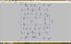
Sim attached - I've grounded the input, and left off a few bits at the input and output. You should be able to scan around the schematic to have a look at voltages. I did this pretty quickly, so I won't guarantee my work!
Does anyone mind sanity checking my transcription of the schematic? I used the attached to work from.
I gotta go to work as well, so I'll have a look again a bit later.
LTSpice
Sim attached - I've grounded the input, and left off a few bits at the input and output. You should be able to scan around the schematic to have a look at voltages. I did this pretty quickly, so I won't guarantee my work!
Does anyone mind sanity checking my transcription of the schematic? I used the attached to work from.
I gotta go to work as well, so I'll have a look again a bit later.
Attachments
- Home
- Amplifiers
- Pass Labs
- Pass Aleph P 1.7 preamp builders thread