B) Match the N-channel to the N-channel and the P-channel to the P-channel. The bias pots will make up for the N's and P's not matching.
So, I need 8 Ps within 100 mV and 8 Ns within 100 mV. Yes?
")
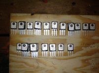
Slow going on the F5TV3 build. I am in the process of collecting all the parts. I have also built a MOSFET match/tester. Hope to match the MOSFETs this weekend.
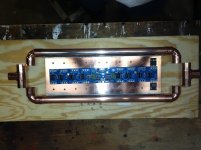
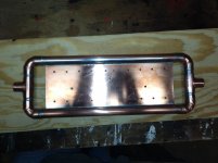
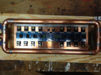
I have decided to go with liquid cooling. I have attached a photo of the cold plate. It is 4" x12" x 1/4" copper plate (4 pounds!) plus the 3/4" copper plumbing. More to follow.....
Any recommendations for a good/cheap 1.5kVA 2X32v toroid? ANTEK?
I have decided to go with liquid cooling. I have attached a photo of the cold plate. It is 4" x12" x 1/4" copper plate (4 pounds!) plus the 3/4" copper plumbing. More to follow.....
Any recommendations for a good/cheap 1.5kVA 2X32v toroid? ANTEK?
Attachments
You heatsink design
It will be interesting to see the thermal gradient of the copper plate, measured near the MOSFETs at the "water entry" and "water exit" ends (i.e., the plate will become hotter and less effective on the right side, assuming the water flows from left to right in your picture......that's part of the problem with many water manifold designs).
It will be interesting to see the thermal gradient of the copper plate, measured near the MOSFETs at the "water entry" and "water exit" ends (i.e., the plate will become hotter and less effective on the right side, assuming the water flows from left to right in your picture......that's part of the problem with many water manifold designs).
It will be interesting to see the thermal gradient of the copper plate, measured near the MOSFETs at the "water entry" and "water exit" ends (i.e., the plate will become hotter and less effective on the right side, assuming the water flows from left to right in your picture......that's part of the problem with many water manifold designs).
I am planning to have a thermal sensor both at the entrance and exit of the cold plate. I have a 1.25 hp hot oil pump that can move 25 gal per minute ( only half kidding). I suspect that the flow rate will overcome the mosfet heat dissipation.
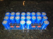
I Vgs matched the Vishay IFR240s and 9240s and now have my two matched quads of each. The copper coldplate is done also.
I have 12 of each of the 240 and 9240 up for grabs, matched within 100 mV, if anyone is interested. I don't know what ask for them, so if you are interested make me an offer. If they don't sell, I will RMA them back to the wholesaler.
I have 12 of each of the 240 and 9240 up for grabs, matched within 100 mV, if anyone is interested. I don't know what ask for them, so if you are interested make me an offer. If they don't sell, I will RMA them back to the wholesaler.
Attachments
Good call.i would be carefull with this PSU's. rectifiers without heatsinking in class A amps is a very very bad idea.
When testing my Krell Klone @ 2.6A output bias from a dual bridge rectifier, the 35A rectifiers got very hot, far too hot to touch.
Adding one smallish 7.5C/W to the pair brought the temp down to barely above hand temp.
i would be carefull with this PSU's. rectifiers without heatsinking in class A amps is a very very bad idea.
Understood. My plan was to move the bridge rectifiers off of the PCB. I am unsure though about how much heat is dispated and thus how much heatsink is needed. Maybe I need another copper cold plate just for the bridges? Any thoughts?
http://www.fairchildsemi.com/ds/DF/DFB2560.pdf
i allways mount the bridges on the bottom. if it's alu.
and i would use some other bridges. i'm not sure that parallel bridges is a good idea. it must end up with current hogging?
maybe a single 50A bridge is a better idea.
I ordered a pair of 50A bridges, one for each channel. I think that I will build another small cold plate to handle the heat dissipation. Thanks for your help.
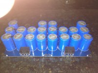
Where can i get a pair of theese pcbs with place for 4 mosfets?
I got these on ebay. There is some concern over whether the manufacturer of the boards has authorization from the designer to produce them. That being said, they are very high quality.
MOSFET High Power 100W Pure Class A Amplifier Thick PCB Turbo V3 Stereo | eBay
- Status
- This old topic is closed. If you want to reopen this topic, contact a moderator using the "Report Post" button.
- Home
- Amplifiers
- Pass Labs
- Starting to build my first F5 Turbo V3