look at close
if you see , while rotating shaft from one position to next , that wiper in mid position is riding on top of both adjacent contacts - then it is make before break
if you see it not making contact with both, in mid position - it is break before make
simple as that
in plenty of cases using either of them is going to be the same, but in case of more complicated construction, chosing proper one is crucial for non-popping operation
I didn't checked,by mistake got those break ones from regular vendor, and used them in one phase of development of Iron Pumpkin balanced, which is sorta complicated having additional relay for automatic switching between SE or Bal In modes, and I pretty much threw through the window entire afternoon, chasing why I have pops on output, whatever I have brain to do..... only to find that damn Lorlin switch is non-shorting
go figure; when dealing with inductive potentials in gadgets, one must obey all rules
anyway, enough babble, do your homework")
I've been thinking about this for a while, the make before break vs break before make. When would break before make be desirable?
I've used these switches in 3 different preamps, one is converted by make before break as actuator for I-Select, also rewiring W's 2018 line stage with one.
The other BA3 FE I'm thinking of just replacing switch with make before break, but since signal will actually be going through it what is affordable make before break?
With I-Select, cheap switch is fine, except it doesn't have best feel to it, and has a slightly loose feel to it in use.
The tube cad is fine in use, just that snapping is annoying.
Oh, also when you say shorting switch, same as Make before break?
Russellc
Last edited:

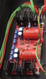
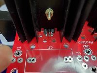
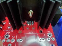
Is these mosfets reverse mounted?
You are right its reverse mounted.
Thanks
gain questions…
Hi again!
I'm still waiting for some crucial parts to continue with this (and other) projects, so I'm dreaming. I'll drive my future F4 with this, but I'll try it with other gear too, and I presume it will be overdriving those conventional amps (Audiolab P8000, ACA, gainclone).
Is the above method ok (I mean, good) to reduce gain? If so, would it be very unvernünftig (foolish) to go with a switch just like yoshida-san did in his Korg-B1? (because of having a crucial part out of the board/into a "long way to ground")?
BUT then I read post #744 onward, and got confused about what the best method—SQ-wise—is for adjusting gain...
Anyway, there's no hurry though, alas!
Change R13 to 200ohm or perhaps even 150ohm.
Gain is R13/R10
Therefore stock is 332/22 = 15
A gain of ~10 would be R13=200ohm (200/22=9)
And reducing R13 to 150ohm would give a gain of ~7 (150/22=6.8)
Hi again!
I'm still waiting for some crucial parts to continue with this (and other) projects, so I'm dreaming. I'll drive my future F4 with this, but I'll try it with other gear too, and I presume it will be overdriving those conventional amps (Audiolab P8000, ACA, gainclone).
Is the above method ok (I mean, good) to reduce gain? If so, would it be very unvernünftig (foolish) to go with a switch just like yoshida-san did in his Korg-B1? (because of having a crucial part out of the board/into a "long way to ground")?
BUT then I read post #744 onward, and got confused about what the best method—SQ-wise—is for adjusting gain...
Anyway, there's no hurry though, alas!
Last edited:
Jfet or mosfet damage
Hi, I need some help. I have proposed to finish my BA3 preamplifier and I have some problems, which I think indicate that I have damaged jfets. What values can I measure and within what range should they give?
A bit of information: I use genuine LS jfets.
Fairchild mosfets.
V Dale resistors and Nichicon and Jantzen capacitors. All bought in mouser and official stores.
I use a psu with an LM317 / 337 source with + -24.2 volts.
I hope your help in case I have to change a transistor or other.
A greeting
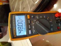
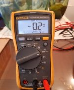
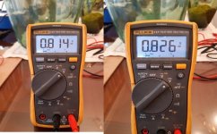
I cannot stabilize the voltage on R 10 and 11. And the DC between R12 and ground oscillates a lot, I still have 10mV as it happens to 200mV.
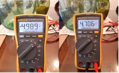
I have measured Vgs in jfets and I have 19 volts.
In mosfets about 5.9 - 6 volts.
These are doubts that come up in the assembly checks that I am doing to know if things are going well.
I have measured Vgs in jfets and I have 19 volts.
In mosfets about 5.9 - 6 volts.
These are doubts that come up in the assembly checks that I am doing to know if things are going well.
Hi, first of all, thanks for the quick responses.
I have a 47Kohm resistor at the output to ground and the input closed in loop with the ground.
I have reviewed the welds and now I notice that the DC is more stable, reaching 30mV with little oscillation. But I am not clear about the values that I have in the jfets.
Thanks a lot
P.S. This deserves a Valencian Paella
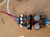
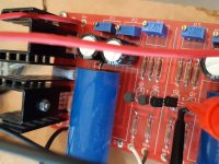
I'm using the Glassware Dual / Bipolar Lv-Reg PSU, and , I made a really stupid stupid mistake, and welded most of the board on the wrong side, until I got to the lm317's. I would not be able to desolder and resolder without destroying this thing, so I did this.....These are the only parts that would have been wrong, it is tight so I soldered top(bottom) and bottom(top), and put shrink wrap on pins.
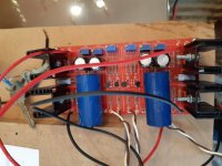
They included diifferent resistors for R#3 to set amperage out to load, 1r, .33r, 3.3r, and 10r. With a 24-0-24 trafo, amps= v/r, this seems like high amperage. I have 18r and 100r, 3 watt resistors on hand. 18r would be 1.3a, and 100r would be .24a. Which is the better choice?
Better brains are always welcome, thank you.
Attachments
- Home
- Amplifiers
- Pass Labs
- BA-3 As Preamp