With the boards disconnected (including earth) both of the PSU LEDs come on without any problems.
I have taken the boards off the heatsinks in order to inspect all the soldering ....all seems OK.
I have tested the LEDS that have been flown out to the front panel with a battery and some cable .... both light up with the battery connections
touching the pads on the board.
All mosfet insulation pads have been inspected (one was found to have two tiny pin prick holes) this has been replaced.
Upon switch on I am still blowing both fuses, does anyone have any suggestions as to what else I can check?
@ItsAllInMyHead:Here are the Mouser part numbers should you fancy a change
652-3296Y-1-502LF
652-3296Y-1-501LF
Sorry for the delay. Somehow I missed your post. Thanks for posting those. They're actually the parts I used.
 Apologies for the lack of clarity in my recommendation.
The parts you linked still have the adjustment on the "top" / opposite the pins. The picture I posted has the adjustment on the "side". That way when you put it on the board and mount the board to the heatsinks, the adjustment screw is on the "top" of the amp instead of pointing to the middle of the amp.
Edited for Clarity - P designation in most of the Bourns pots versus Y.
Hope that helps explain. Fortunately all my amps are set up and running, but I will be using the other pot orientation where practical for future projects.
BTW - How's the amp coming along?
Last edited:
Hi Dennis,
The first photo of 1566 shows the brown wire in the middle coming from the IEC , the darker brown wire to the right goes to the transformer. The two blues on the left are from the IEC and to the transformer.
These are the fuses ordered from Amazon France,2 de 10x Fusible temporisé (T) en verre 1.25A / 250VAC 5x20mm.
Temporisé translated means timed, which I think is slow blow but I could be wrong.
I took the values for these fuses from the F4 instructions.
Thanks.
66 Deg, AKA Simon.
My toroidal transformers with 500VA and 230V/50Hz at the primaries and
2x24V at the secondaries need a 2.5AT fuse (T stands in Germany for slow blow = träge).
My 1000VA toroids at 230V/50Hz (prim.) and 2x24V (sec.) are rated at
5A fuse min. on primary side.
So I would estimate that you will land anywhere between 3.15A (slow blow) or probably more to 4 A (slow blow).
I would test it with only the PSU hanging on the tranny. And I hope you have a
thermistor (CL60 or similar) or a soft start board in front of this transformer.
At start up this big sucker will suck energy!
And use a light bulb tester.
My thoughts. I can be wrong.
Greets
Dirk
Simon,
Your transformer is pretty large (756VA) and I suspect a slow blow 1.25A, will
blow on startup, even with a thermistor.
I'm thinking something closer to 3A may be needed.
Hopefully others will chime in.
Dennis
I used 1.5A slow blow on a 1500VA transformer with 300 000uF on rails.
I used a 3 seconds soft start that charges the capacitors trough 20Ohm NTc's.
If soft start is already implemented using CL60's in series with transformer primary ... the inrush should not blow the 1.xA fuse. But start low ; and blow your way to stable
forgot : I am in 230V land.
Last edited:
why isn't a 60-100W bulb used in the primary of the transformer for power up at the first time?
I would do
1. put a bulb in the primary
2. disconnect everything from the transformer, power on, measure the AC voltage on the secondary, ok, power off
3. connect the rectifier bridge, measure the DC, ok power off
4. connect to the power board, measure DC, ok, power off
5. connect to F4 board, still with bulb in, power on and follow 6L6's instruction to watch the bulb
you could isolate the problem
Pass DIY Addict
Joined 2000
Paid Member
Also use your DMM to check to make sure you don't have other, invisible, shorts between your mosfets and the sink. Check all three pins for continuity with the sink (usually middle pin is connected to metal pad on back). There should be none.
If you did not properly de-bur your mounting holes, it will short rather easily. This is the primary reason I've switched to using Aluminum Oxide Ceramic insulators - they have better thermal transfer than just about anything else. I've been burned by a tiny sliver of aluminum that pierced a silpad before.
4180G Aavid | Mouser
At start up this big sucker will suck energy!
when connected to mains the ones that cause the inrush are the supply capacitors and the actual consumer(class A stove)
....transformers.... actually upon mains connected .. in the first 2ms they have infinite resistance (as opposed to the capacitors in the supply that basically shorts the secondaries)... then ...nominal.... they're big ol coils'.
If you need just use this, shows what happens hertz by hertz
PSUD2Thanks for everyone's input, I will do some further tests and report back.
BTW I can't see anything about a light bulb test on page one could anyone let me know where I can find this info?
Try here... biasing section...
BA-3 Amplifier illustrated build guide
But visual check after a day or two of detaching to actually check transistor/diodes/capacitors orientation and power source polarity without assuming anything ... beats the hell of the variac/bulb safety net.
And more into depth and really helpful of understanding Mr Pass's beasts when in trouble:
Your F5 blew up, now what do you do? - diyAudio
A light bulb tester is like an extension cable where the hot cable from your
wallwart is interrupted / cut and a light bulb is made inbetween.
Very good tool (easy selfmade) to test your amp at first startup for shorts
without destroying it. Works like a current limiter and can be a `life-insurance'
for your new amp!
Check pics.
Greets
Dirk
wallwart is interrupted / cut and a light bulb is made inbetween.
Very good tool (easy selfmade) to test your amp at first startup for shorts
without destroying it. Works like a current limiter and can be a `life-insurance'
for your new amp!
Check pics.
Greets
Dirk
Attachments
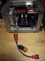
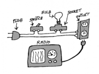
You put the light bulb tester between your amp and the walloutlet.
If you switch your newly built amp on the bulb will shine pretty bright and then will dim down or go off - then your amp is o.K... - No shorts.
Doesn't work with LED-bulb! You need a classic filament lamp.
Greets
Dirk
If you switch your newly built amp on the bulb will shine pretty bright and then will dim down or go off - then your amp is o.K... - No shorts.
Doesn't work with LED-bulb! You need a classic filament lamp.
Greets
Dirk
Pass DIY Addict
Joined 2000
Paid Member
Excellent advice!
I NEVER fire up an amp for the first time without using a dim bulb tester (well, at least since my very first project that blew up when I flipped the power switch for the first time...). Sometimes, I'll use both a dim bulb and a variac to see how things behave as you ramp the voltage up.
Using a dim bulb tester will deliver far less working voltage to your amp, but should allow you to verify that offset figures are ballpark, that voltage is making it to your output fets, and that you can adjust the bias level as expected. An amp with a dim bulb in the AC loop may have some hiss/noise/static/whatever (because voltages are low), but it should actually allow you to verify that the amp does indeed operate. You amp, with the dim bulb in place, should still produce music output with a test speaker.
Building the Pass/Firstwatt F4
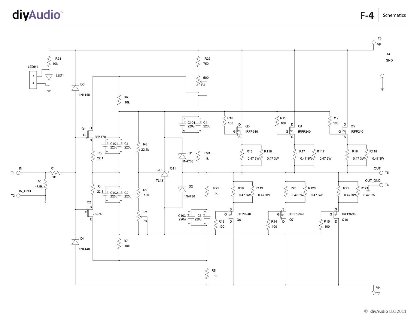
Please comment away if you desire.
Also please feel free to ask any F4 questions here, and if you would like to post photos of your F4 completions, old or new, please do!
I don't see your fantastic build-guide-images anymore. Is there something happening?
- Home
- Amplifiers
- Pass Labs
- A guide to building the Pass F4 amplifier