Zen Mod I needed information, to weaken the amplifier (I need only 7-8W) what should I change compared to the original scheme?
- remove two pair of output device?
-descrease the power supply voltage?
-change the value of bias setting?
-change the value of some component?
Precise that I currently have an E88CC SRPP Preamp with a gain of about 28-29dB and a pair of heatsinks of the dimensions of 35x125x250 mm.
Thank you in advance
I've got all the parts and am ready to build. I was hoping to build an integrated in one chassis with an Aikido 12vac driving for now. The torroid I got was this:
Airlink Transformers
The plan was to draw from the same Tx the 18vac for the Aikido board to keep the supply simple. Is there any technical issue not to do it like this? I ask because the PS sextupler circuit of the Aikido 12vac is new to me and I don't know it's effects, if any on, the Tx.
(I'm planning to adjust the RC values on the Aikido board to use 6dj8 to keep the gain up rather than the 12au7 when using 18vac standard.)
Thanks
Choky,
Friend of mine came last night for audition the F4 with my MFA line clone. He asked if I could build him the F4.
I found my stock and luckily I still have 2 sets of matched p channel and a set of n channel but the other set 240 has only 2 matched and the third is about 0.03v out of range. Could it be a good idea to try them on or buy a matched triplets 240.
Albert
The third N channel is 0.03 different than the other two? That's close enough to be completely, utterly and exactly dead-on matched, and you'll have more thermal variations than that within the three.")
Thanks. I can go ahead. Pictures will be posted.
Pass DIY Addict
Joined 2000
Paid Member
To put this in perspective, Fets seem to measure Vgs somewhere in the neighborhood of low 4.x volts. Let's call it 4.20 for argument sake. 4.20v vs 4.17v represents somewhere near 0.7% matching tolerance. Generally, matching within 1% is considered excellent and matching within 10% still works great. I have some memory of Nelson stating that Pass Labs matches devices to within 10% tolerance.
Pass DIY Addict
Joined 2000
Paid Member
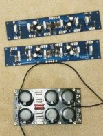
Have the 5k pots installed and have the boards check without the mosfet connected. I put +/- 22v from the bench supply and have the following numbers.
R3/4 10 ohm
R9 4.7K
R8 22k
P2 at middle of 250 ohm
R23 changed to 15k, for the reason that I don't want the LED too bright.
mA meter series with positive
Board 1). 86.5 mA
Board 2). 86 mA
The voltage at R3/4
Board 1). 73.8mV 74.5mV
Board 2). 73.1mV 74.3mV
240 gate reference to ground
P1 at max 1). 6.49v 2). 6.81v
P1 at min 1). 4.26v 2). 4.94v
9240 gate refence to ground
P1 at max 1). 6.18v 2). 6.60v
P1 at min 1). 4.02 2). 4.45v
Do all the above numbers look right?
Thanks
Albert
Last edited:
Have the 5k pots installed and have the boards check without the mosfet connected. I put +/- 22v from the bench supply and have the following numbers.
R3/4 10 ohm
R9 4.7K
R8 22k
P2 at middle of 250 ohm
R23 changed to 15k, for the reason that I don't want the LED too bright.
mA meter series with positive
Board 1). 86.5 mA
Board 2). 86 mA
The voltage at R3/4
Board 1). 73.8mV 74.5mV
Board 2). 73.1mV 74.3mV
240 gate reference to ground
P1 at max 1). 6.49v 2). 6.81v
P1 at min 1). 4.26v 2). 4.94v
9240 gate refence to ground
P1 at max 1). 6.18v 2). 6.60v
P1 at min 1). 4.02 2). 4.45v
Do all the above numbers look right?
Thanks
Albert
Jim, Choky,
I can't remember what I did for my amp some 10 years ago and can't find the notes for it. I remember I need 8-9v on those gates to operate , is it? What should I check so to up the voltages to target? The total current for the front part should be around 10mA but I only have 8.6mA on each. R3/4 is working fine with around 73mA on each.
Thanks
Albert
I check all the pages including the F4 thread for anything talking about adjustment and tuning of the amp. I finally find out I made a big mistake on checking the gate voltages by referencing the ground. I should check across the gate to gate. 😄
I have them firing up and breaking in. I set both channels at 130mv to start and it drifting up to 166 after about 40 minutes. I thought it is normal. MOSFET at 36c and heatsink 30c. See how it goes.
I have them firing up and breaking in. I set both channels at 130mv to start and it drifting up to 166 after about 40 minutes. I thought it is normal. MOSFET at 36c and heatsink 30c. See how it goes.
- Home
- Amplifiers
- Pass Labs
- A guide to building the Pass F4 amplifier