in both channels increase R8 from 22K1 to 33K
in Mu channel ( undecided one ) replace TL431
report
be sure to start with maxed P1 ; check with ohmmeter , do not trust anyone with rotation directions
@JeffYoung and @Zen Mod -
I think I have things sorted re: a sequence.
For Channel 2 (no movement)
1) Already removed from chassis for minor surgery.
2) I am in process of reviewing spec sheet again for TL431 I bought against schematic to make sure I put it in properly. I admit that I don't remember if I checked this prior or just went with the outline on the PCB. If so, bad me. Soldering looks proper, but I was smart enough (lucky) to buy spares, so I will swap either way and report.
3) If it behaves like channel 1, then that gets me one step closer.
Channel 1 and Channel 2
4) Increase R8 from 22k1 to 33k. I will check my "inventory" (pile of bags) to see if I have any left over from another project or if I have a 10k or so to put in series with a bit of a temp solution.
If gods are smiling, I can accomplish 1-3 in a few hours. 4 will depend on if I have parts.
Once again - thank you! Much more reading and learning ahead for me. I am somewhat certain what we are trying to accomplish, but there is no way I would have diagnosed this properly.
@66deg - Good luck on yours too!
Whilst everyone was very kindly pointing out my error I was scratching my head and doing various tests with different settings on the DMM and finally came to the same conclusion that my R3 should read 22RIF on the label. Had I checked in here a little earlier my brain would not now be aching quite so much. Thanks for all your input, I'm away for a couple of
weeks so will get back to you with phase 2 later.
@Jeff, thanks for the explination, I did my first bit of learning on the ACA with all the coloured bands....I liked them!
weeks so will get back to you with phase 2 later.
@Jeff, thanks for the explination, I did my first bit of learning on the ACA with all the coloured bands....I liked them!
not same poster...
Why is there no emoji for forehead-slap? This'll have to do:

-Ma, look what I found!!
-OK, Sonny, that'll teach ya not to trust anyone on the Internet ...... now, eat yo'r Porridge and go to bed!

Hi ZM - I was not sure if this was related to my issues. So, I made some tea and reviewed the differences in the schematics between what you posted, the schematic I used, and the parts I installed / my build sheet. Because I'm new to this, I always take the schematic and create a build sheet / parts order sheet. When I install the parts, I pull them from my "inventory", check and/or test the value against my build sheet and the schematic, install it, then tick it off both the schematic and build sheet. Then, I inspect the soldering for that part.
My build matches the schematic I posted vs. the one you posted.
Here is what I noticed -
Q1 and Q2 are different parts as are their corresponding (not sure if this is correct term) source resistors. I checked the specs on 2SJ108 and 2SK370 vs. 2SJ74 and 2SK170 respectively, but honestly that is a bit out of my level of expertise. If this is relevant, please let me know. It's on the input buffer side, so I don't think so. Also those Toshibas seem to be the "gold parts", so I think their use in the F4 is common. I did read about removing the input buffer for the F4, but I don't want to mess with that now.
R8 is 27k4 vs 22k1. This could be relevant based on what you were asking me to do... increasing R8 to 33k.
D1 and D2 have a different part number - 1N4736 vs. 2N4736. I checked the specs and reviewed previous posts and questions in the thread. Should be no worry here.
Gate resistors for FETs are 150R vs. 100R. This.... again, I admit makes me scratch my head.
I love that you guys will teach a bit along the way. I make every effort to understand and digest.
I don't see anything in the r0 schematic compared to the DIY 2011 that causes me dramatic pause. Did I miss something critical?
As always with thanks! No porridge around, but I can put together a bowl of oatmeal with some cinnamon.

I'll continue moving with the plan in post #1501 if you were not subtly trying to tell me I've missed THE key thing.
Why is there no emoji for forehead-slap? This'll have to do:
Because I'd have used it far too much...
Hi Patrick,
+1 to what ZM said.
The schematics ZM posted came from the current F4 manual (p.13):
http://www.firstwatt.com/pdf/prod_f4_man.pdf
The one you used was a slightly older version.
Usually when you run out of range with the pot when you are trying to set
the bias, a solution is to increase R8 so the TL431 can give a higher voltage.
Dennis
ZM, Dennis, and Jeff (and everyone) -
Thanks again for all the help. I think we are getting closer.
I deviated from the plan a bit. Because I essentially have to disassemble the whole amp including moving the transformers and yanking the power supply to get the amp boards out, I went ahead and changed the TL431 and upped the resistance of R8 to 32K1 (I added a 10k in series) all at the same time.
Good news is that we have voltage movement with R1 and increased voltage.
With the pot all the way CCW - I have 3V86. With it all the way CW - I have 5V21.
The sad news is that I still have 0V across any of the source resistors.
I am holding off on upping the resistance on R8 for Channel 1 until I get Channel 2 settled. I am not the best at desoldering, so I'll leave one board alone for now.
Once again, thank you! I'm humbled by the support.
If I'm supposed to get between 6 and 8 V - Do I need to go up further yet in resistance? My 3 part averages for Vgs (if I measured them properly) was:
9240 first triplet - 4.11x
9240 second triplet - 4.12x
240 first triplet - 4.09x
240 second triplet - 4.12x
These readings were without heatsink after 30s at 22V0 & 0A37
I read they needed to be around 4 in one of the Papa articles, so I assumed these were OK for the purpose.

The best news is that the SissySIT is keeping me calm as I go through my learning...
Thanks again for all the help. I think we are getting closer.
I deviated from the plan a bit. Because I essentially have to disassemble the whole amp including moving the transformers and yanking the power supply to get the amp boards out, I went ahead and changed the TL431 and upped the resistance of R8 to 32K1 (I added a 10k in series) all at the same time.
Good news is that we have voltage movement with R1 and increased voltage.
With the pot all the way CCW - I have 3V86. With it all the way CW - I have 5V21.
The sad news is that I still have 0V across any of the source resistors.
I am holding off on upping the resistance on R8 for Channel 1 until I get Channel 2 settled. I am not the best at desoldering, so I'll leave one board alone for now.
Once again, thank you! I'm humbled by the support.
If I'm supposed to get between 6 and 8 V - Do I need to go up further yet in resistance? My 3 part averages for Vgs (if I measured them properly) was:
9240 first triplet - 4.11x
9240 second triplet - 4.12x
240 first triplet - 4.09x
240 second triplet - 4.12x
These readings were without heatsink after 30s at 22V0 & 0A37
I read they needed to be around 4 in one of the Papa articles, so I assumed these were OK for the purpose.

The best news is that the SissySIT is keeping me calm as I go through my learning...
Last edited:
@ItsAllInMyHead, are you sure you Ns & Ps are the right way around? I can't see because of the big washers on them.
And double-check that your positive rail is positive and the negative negative.
Checked again for good measure. You'll probably need to trust my eyes with magnification better than the pics, but I had checked these previously also, so I'm very confident I've minded my Ps and Ns.
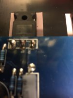
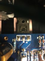
I only removed the fender washers for two, because getting to the others requires removing the PSU. I took the pic of representative pieces. I then made sure that what I assume are the date and/or lot codes that are visible on the others with the fender washers still in place. AA vs. AJ was easy to discern.

You can make out the 9240 Q7 and P.

A bit better shot of the 240 with the N. Harder to make out Q3
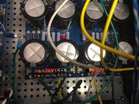
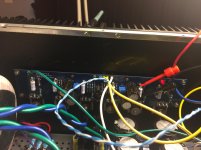
I checked the rail voltages once again. Yep, pos is pos and neg is neg. This PSU has been used in a couple other amps. You can see the green (V-) and blue (V+) going to their respective places on the amp boards along with showing the clips across the source resistor for where I was measuring.
-26V1 and +26V1 (so it seems to correspond with no load).


Once again, I can't thank you enough for the efforts!
what is the voltage across R9 , when you max gate-gate voltage with P1?
R9 ref to schmtc I posted in #1500
I verified the R9 in both schematics is same position. So, it should be correct for one you posted in #1500.
With the max gate-gate voltage as measured previously with red at gate resistor of 240 and black at gate resistor of 9240 - 5V21 is max gate voltage with new Voltage regulator and new R8 of 32K1.
The voltage across R9 is 1V24.
Thank you!
OK. Shot in the dark. Can you take a look at Q11 (the voltage refernce).
Is it possible you have a low reference voltage version of 431 there?
(Something like AZ431L)
I truly appreciate all the input. I used this part.
You may be onto something!!!! Good gracious...
595-TLV431ILP
TLV431ILP Texas Instruments | Mouser
from some reason , you have funny TL431
"real" one is having 2V5 as ref. voltage and there is a reason why is your voltage low
so - I retract what I said that with low ref resulting voltage is going to be higher , dumb ZM , hungry and caffeine starved
now - either wait for proper TL431 , or double that 33K - either put another one in series or go for 68K (as R8)
under condition that you have now same voltages (even if low) on both channels , that will be the cure
"real" one is having 2V5 as ref. voltage and there is a reason why is your voltage low
so - I retract what I said that with low ref resulting voltage is going to be higher , dumb ZM , hungry and caffeine starved

now - either wait for proper TL431 , or double that 33K - either put another one in series or go for 68K (as R8)
under condition that you have now same voltages (even if low) on both channels , that will be the cure
Last edited:
To all!
A hearty thank you! There is absolutely no way in the world I could have figured that out.
I have been scanning the spec sheets in Mouser. Time to learn more about voltage reference devices. I'll scour my resistor pile and see what I can cobble together to get close to 68k.
I'll also mark my parts bag for these TL-431 so I know for sure not to use in other amps without further understanding and reviewing of the full spec sheets.
I'll get to work and report findings.

Yeah, adjusting R8 is probably the simplest thing right now. (I hate desoldering 3 pin
devices.)
Quite the amusing problem you had; Wrong version of the part, and one that was dodo.
I am glad this is intellectually stimulating / amusing for the folks around here that really know what the heck goes on within an amp. Truthfully, without the community here, I'd be lost in the wilderness. Just when I think I can sort of get to the bottom of certain things... sheesh. I am learning though and having a ball. So there is that.
Fortunately, I think I have a pile of 47k5 resistors. 47k5+22k1 should get me close enough for government work. If not, I can use 3 22k1s I have in front of me for a pretty loop
- Home
- Amplifiers
- Pass Labs
- A guide to building the Pass F4 amplifier