Hi, I have a bit of a newbie question as I am thinking of building an F4 and would like to know if the TU-8100 PCL86 is compatible with the F4? The only specs I have found are as follows.
Rated Output: 2W per channel into 6 ohms at 10% THD
Rated Input: 500mV(INPUT-1), 150mV(INPUT-2)
Frequency Response: 23-33,000Hz
Residual Noise: 40microV(IEC WEIGHTING)
Corresponding Speakers: 4-8ohm
Output Terminal: Binding post (Banana plug compatible)
Input Voltage: 12VDC, approx. 2A (fixed)
AC Adapter: World compatible 12V@4.17A Switch mode power supply
Thanks.
Is this sold as a kit? I'd like to buy one please.Placeholder for 6l6
https://www.passdiy.com/project/preamplifiers/b1-buffer-preamp
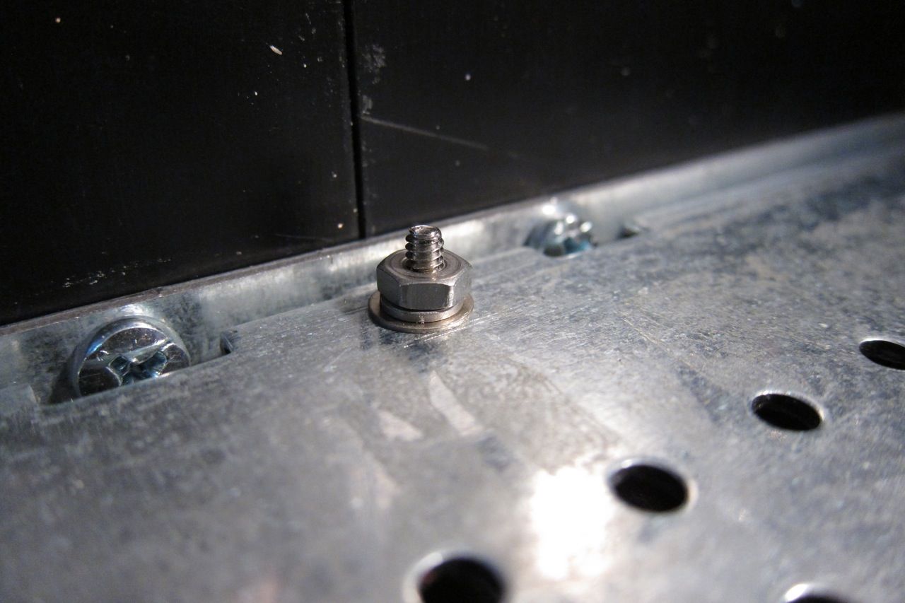
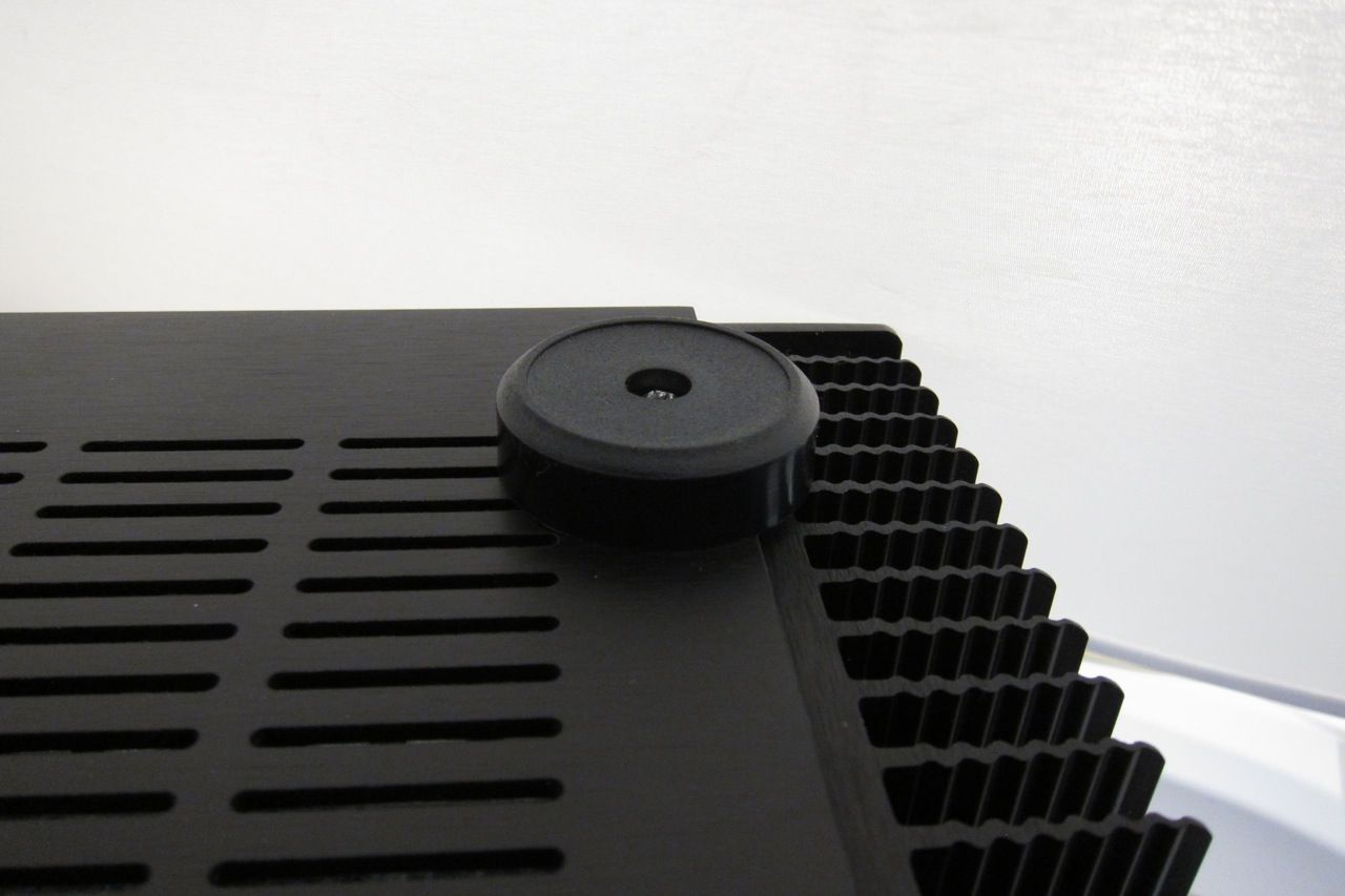
The eagle-eyed among you noticed that I had the perforated baseplate installed upside-down, so I needed to flip it over and mount it so the screwheads under the steel perf would not touch the actual baseplate.
The provided hardware is a bit short, so I needed to improvise - this is DIY, after all, so no big deal.
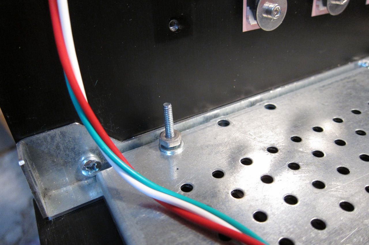
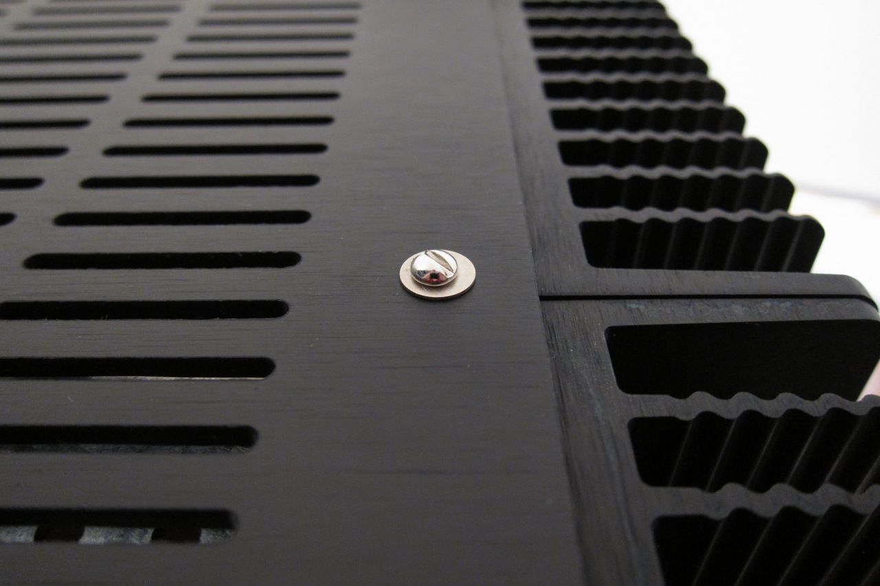
You can see here the perforated baseplate installed correctly.
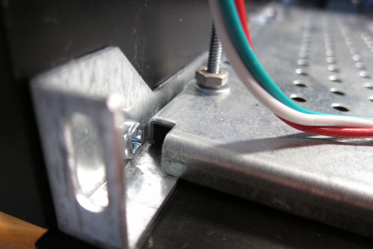
When searching for screws, they always come in 2 lengths - too short and too long...
But those screws on the 4 corners do need to be longer than the center screws because the chassis feet are mounted with them.
Amp bottom
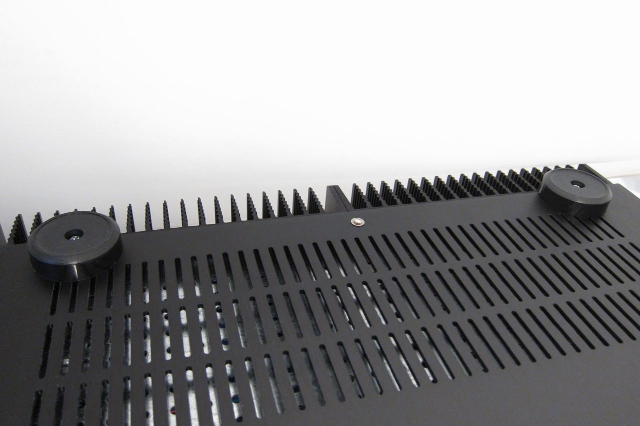
When complete, each side of the amp bottom should look like this.
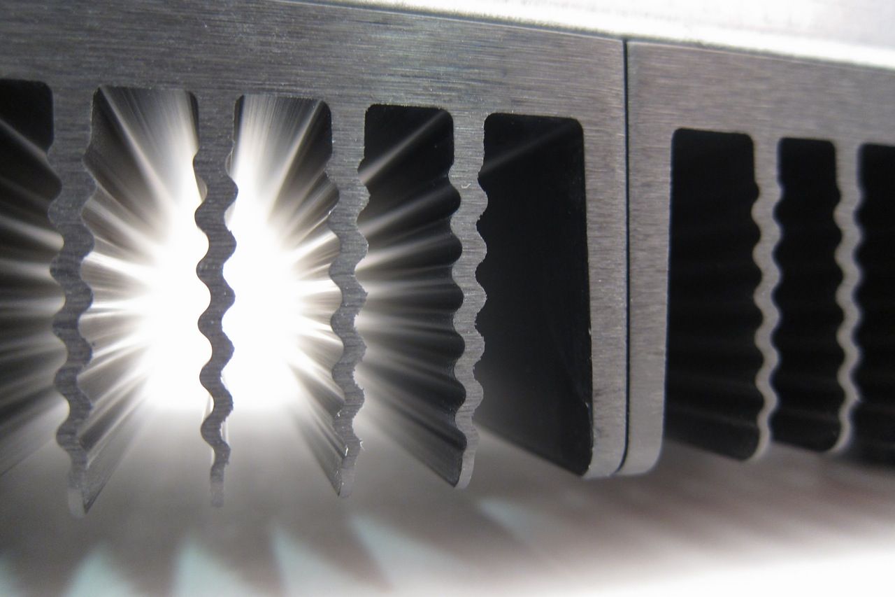
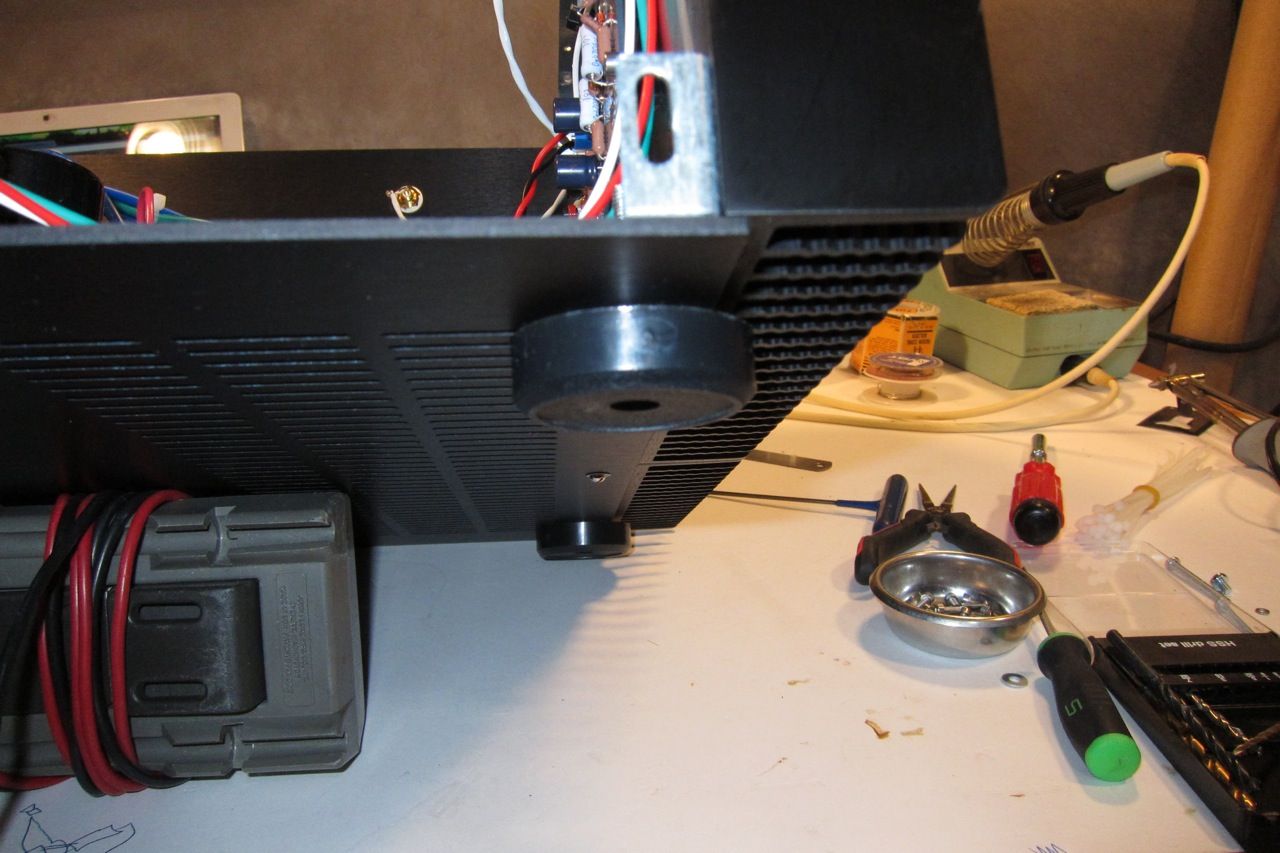
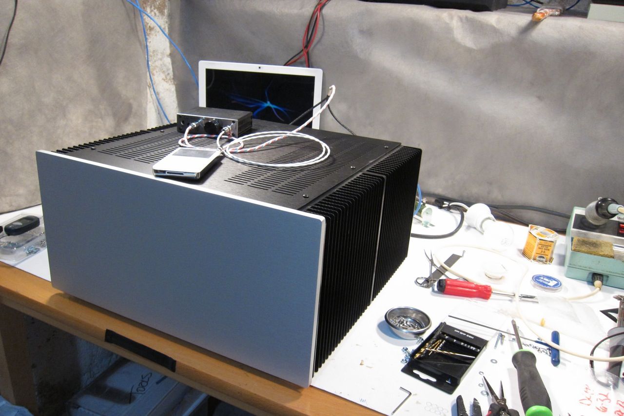
A neat photo highlighting the extrusion profile of the big heatsinks.
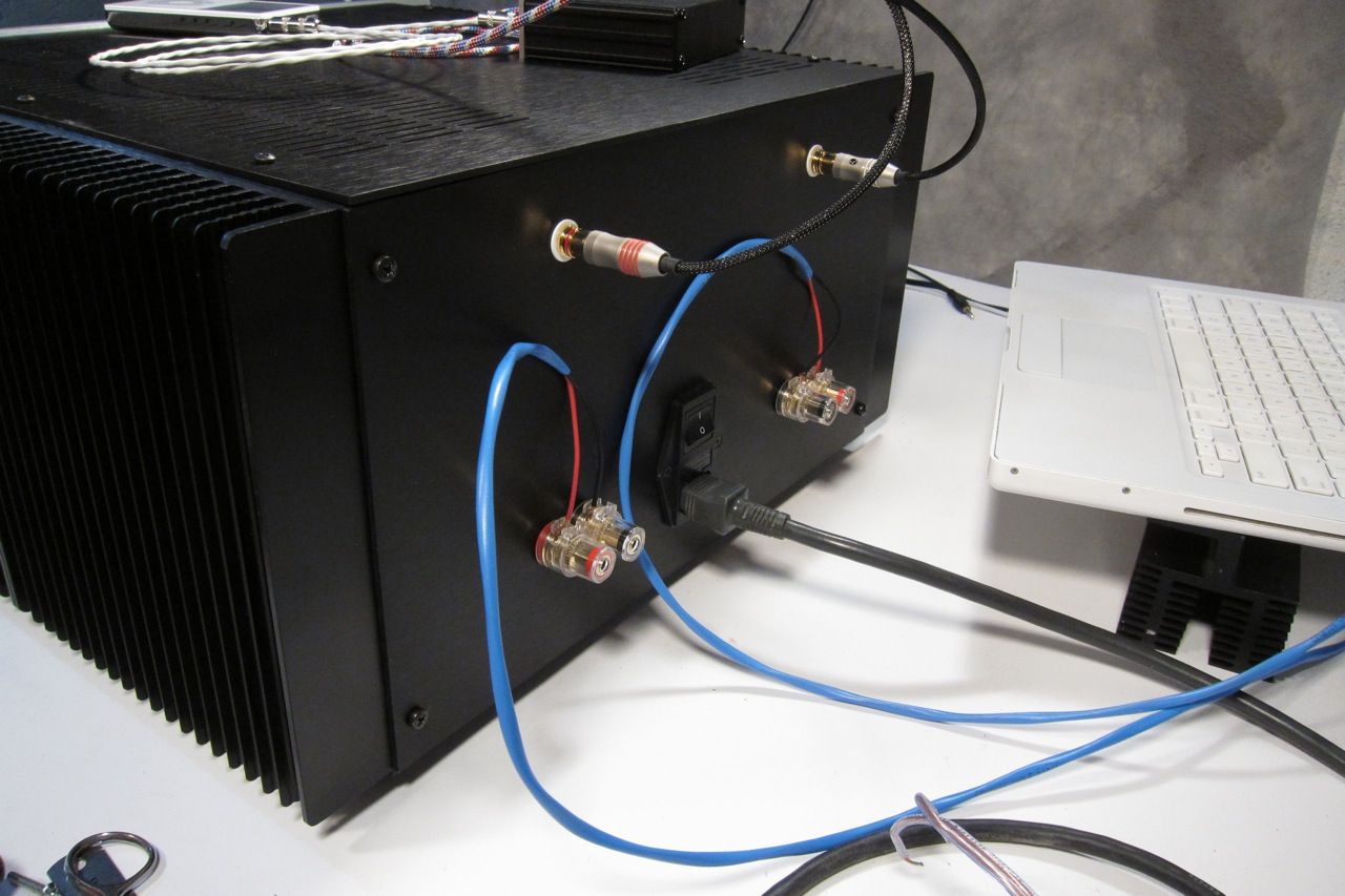
That completes it, the chassis is quite simple to assemble, and the pre-drilled back makes things really simple.
The amp goes together with very little effort -- it's a rewarding project.
You can also see in these photos that the 5U 'Big Amp Chassis' is, in fact, as advertised, being quite enormous.
I used the 5U because I had it, and it will be used for a number of these guides. The 4U 'Jack of all Chassis' would be plenty for this amp.
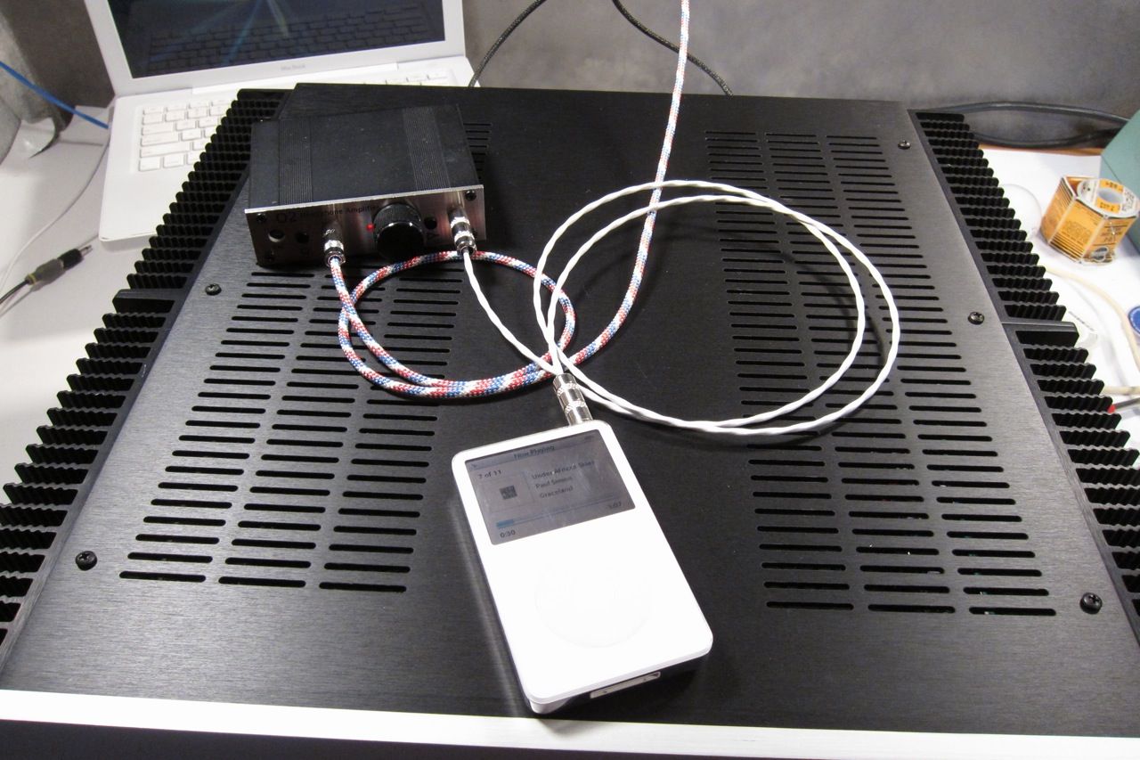
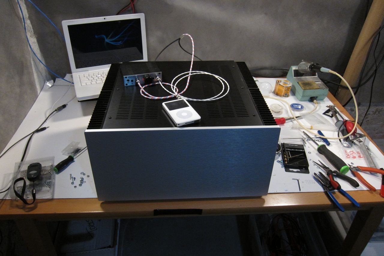
For now I am driving the F4 with an O2 Headphone amp, as it is the only 'preamp' I have that can swing enough volts (7) to give real volume, although not to clipping. Still, has enough drive for my current setup, so I'm not wishing for something else. It also sounds fantastic. Seriously.
An ImPasse will be built to drive this amp, and I am also very interested in the Pumpkin / Shunty.
So how does it sound? Well, there is not a lot to say because it's so incredibly neutral, it sounds a lot like the O2, which is very neutral and musical itself.
I have been finding the amp extremely difficult to listen to critically and listen to the amp, as I find myself singing along to whatever I play… Every time. It's really cool.
How does it compare to the F5? That's very hard to describe - you the F5 is a fantastic sounding amp, no question. Better than any other amp I have ever built, tube or SS. It (the F5) will make you understand the whole 'Class-A' mystique, and you will be very happy that you built it, because it delivers on it's promises. It truly is a great amp and a great design.
The F5, when compared to the F4 is, in my opinion, is a bit boring. The F4 is that good. . But remember it comes at a price, specifically that you will likely need a dedicated preamp for it. (Or you could bi -amp it with a flea-powered tube amp, but that's a different story. See the manual for more info.)
Some interesting measurements concerning bias levels -
Here are some quick and dirty measurements I did looking at various levels of bias on the F4. ( +/- 22.5V rails )
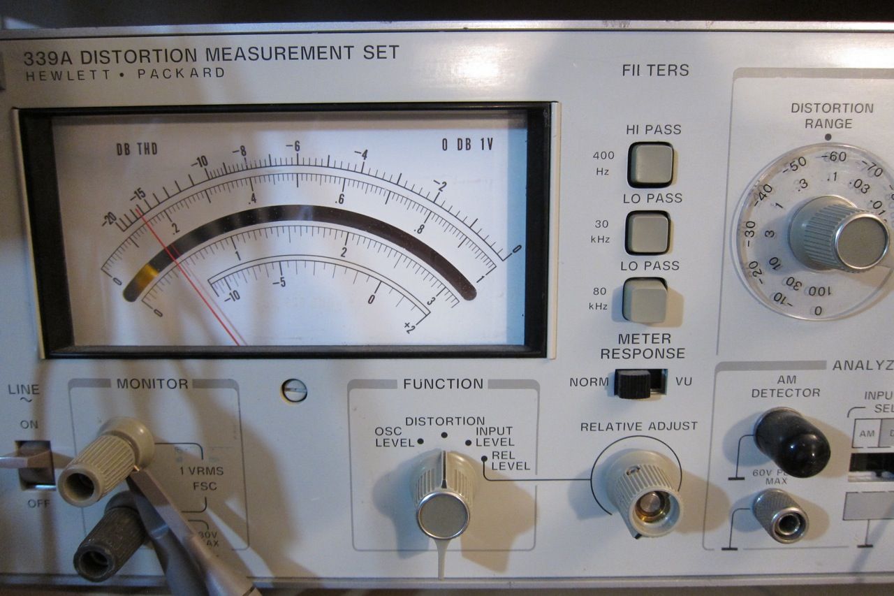
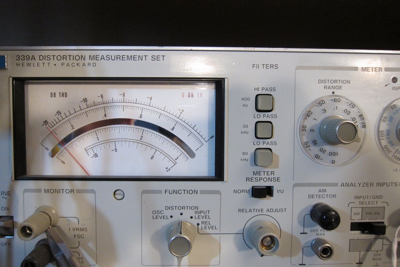
The conditions are, amplifier to normal temperature, one channel driven (because I cant read 2 at once), input to amplifier 3V 1.1kHz sinewave from 339A, distortion read across 4ohm 100W dummyload resistor, oscilloscope and FFT connected to HP 339A monitor, which was outputting the residual distortion waveform.
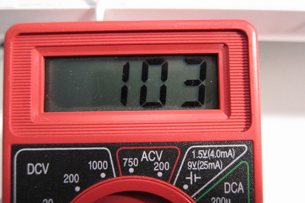
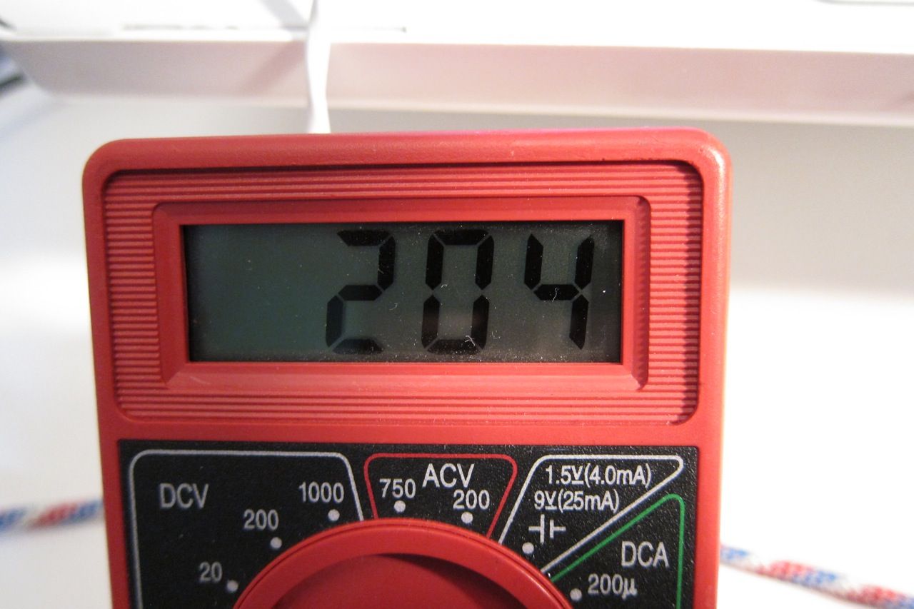
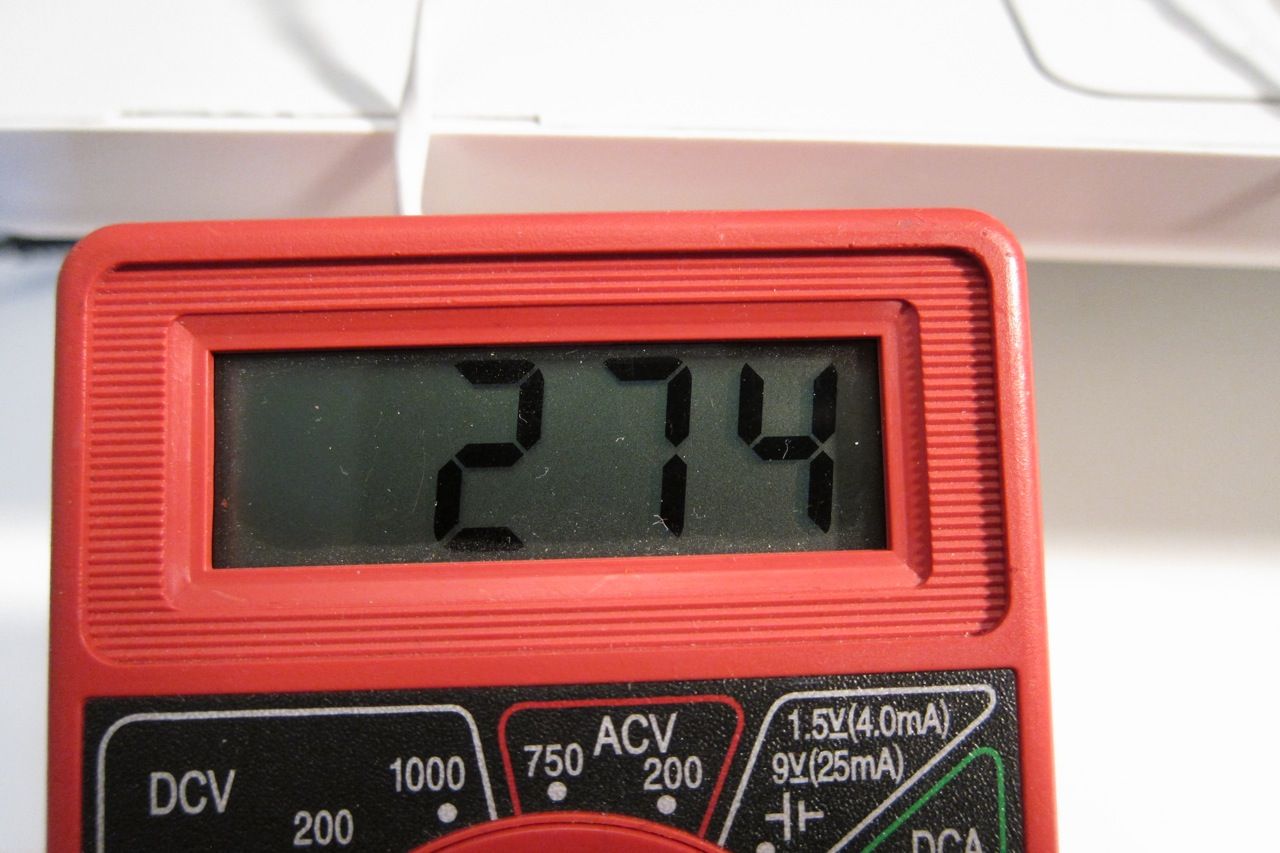
Bias measured across a .47 source resistor. (This is 1/2 the normal level, for illustration's sake)
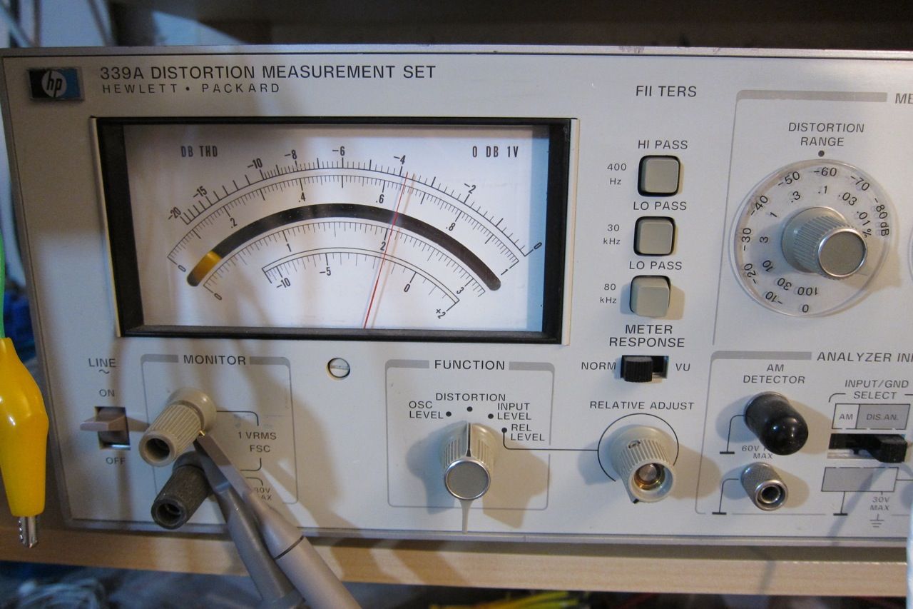
Distortion (Meter is set to the .1 scale, look at the arc above the mirror, here showing .065%)
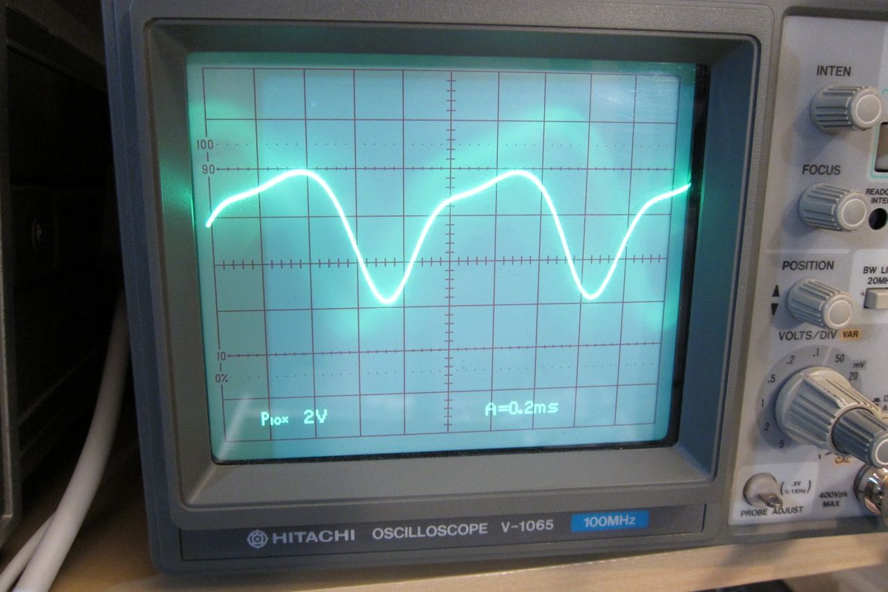
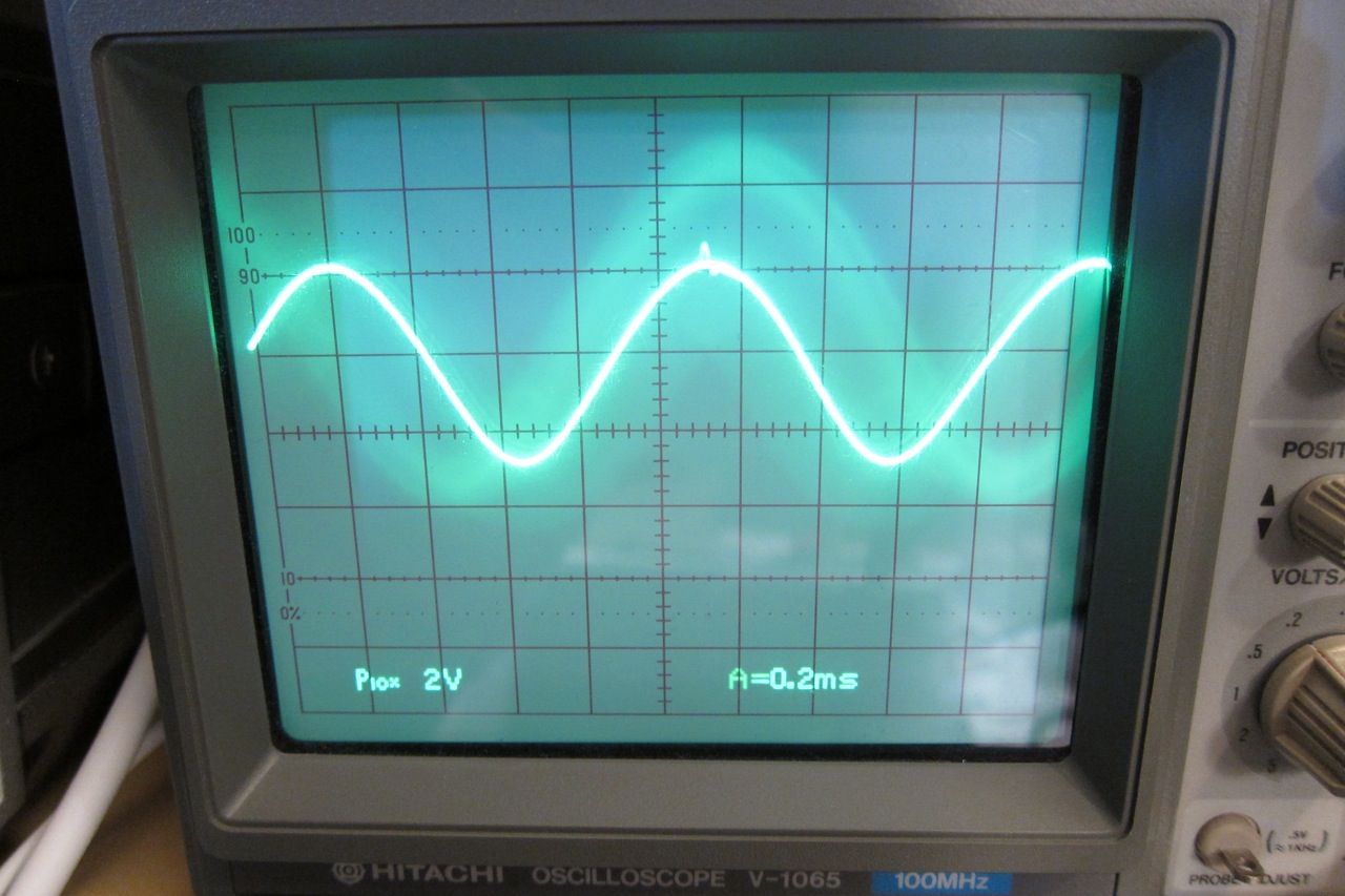
Here is the shape of the distortion residual. (No distortion would look like a perfect sinewave.)
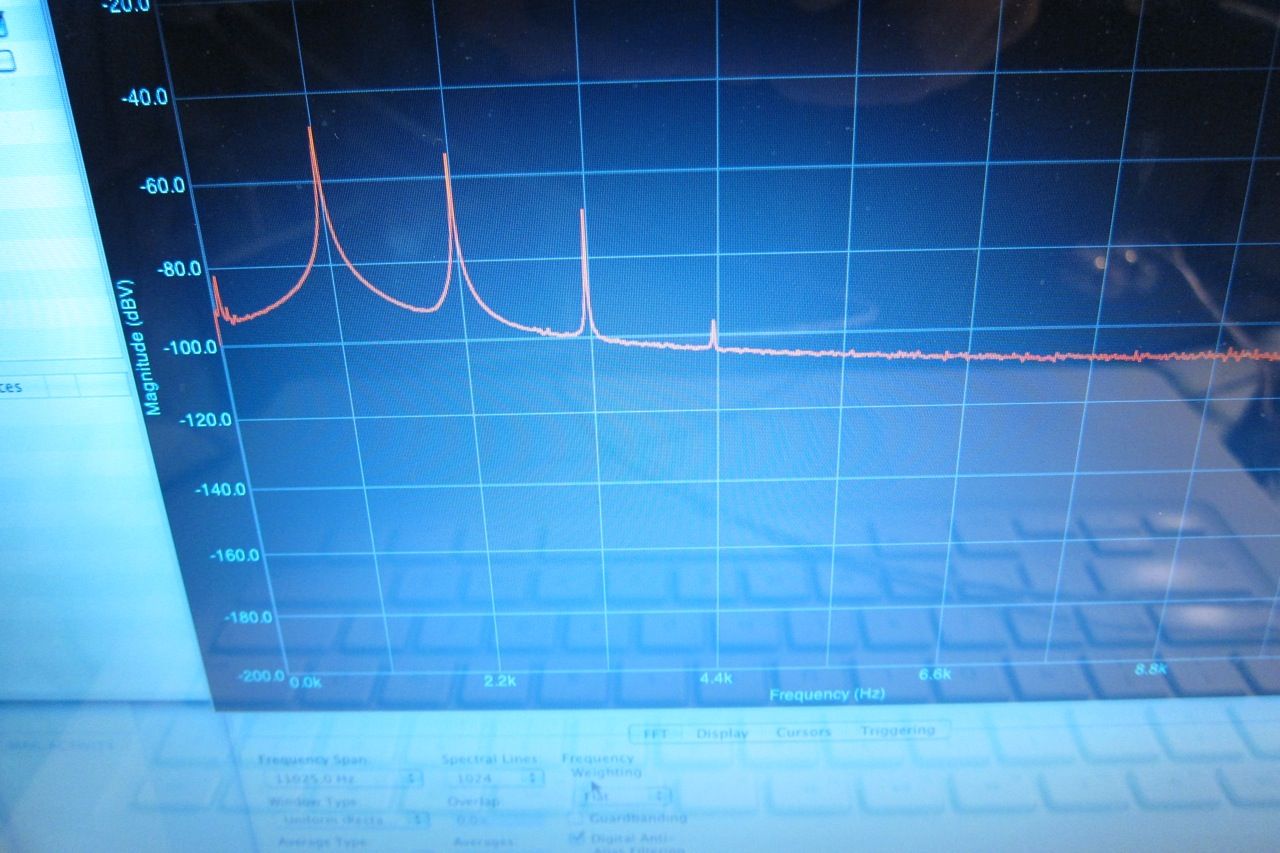
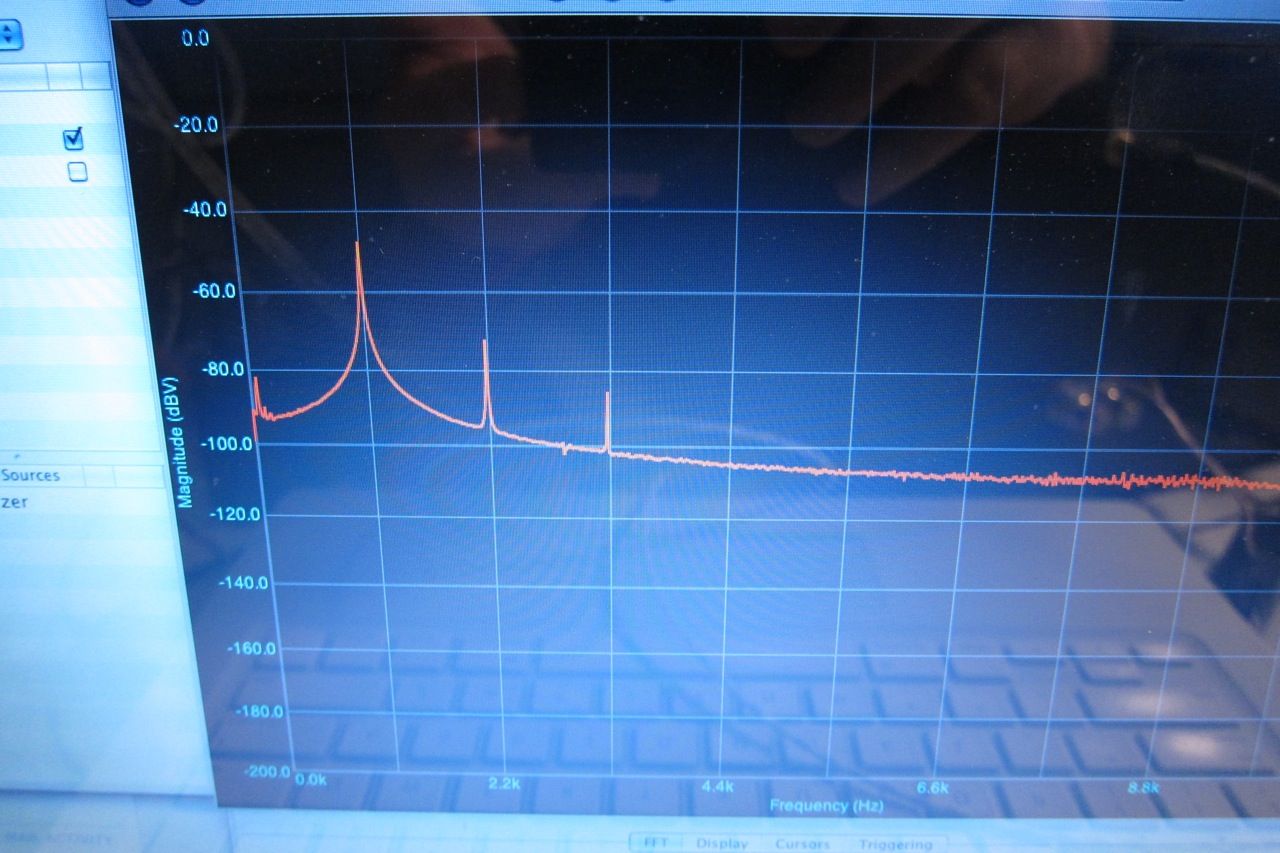
FFT of the distortion residual. (please excuse the photo of the screen. The next time I do this I will get screenshots.) The 1st peak at 2.2k is the fundamental. (2.2k chosen as it aligns with the gridlines. ) Looking right, he 2nd peak is the 2nd harmonic, the 3rd peak the 3rd harmonic, and the 4th peak the 4th harmonic. Higher level harmonics are not visible, as they are very small and lost in the noise.
Now let's increase the bias to the recommended amount, 200mv measured across the source resistors.
Distortion has now decreased to .016%. All that has changed is the bias. What a marked difference!
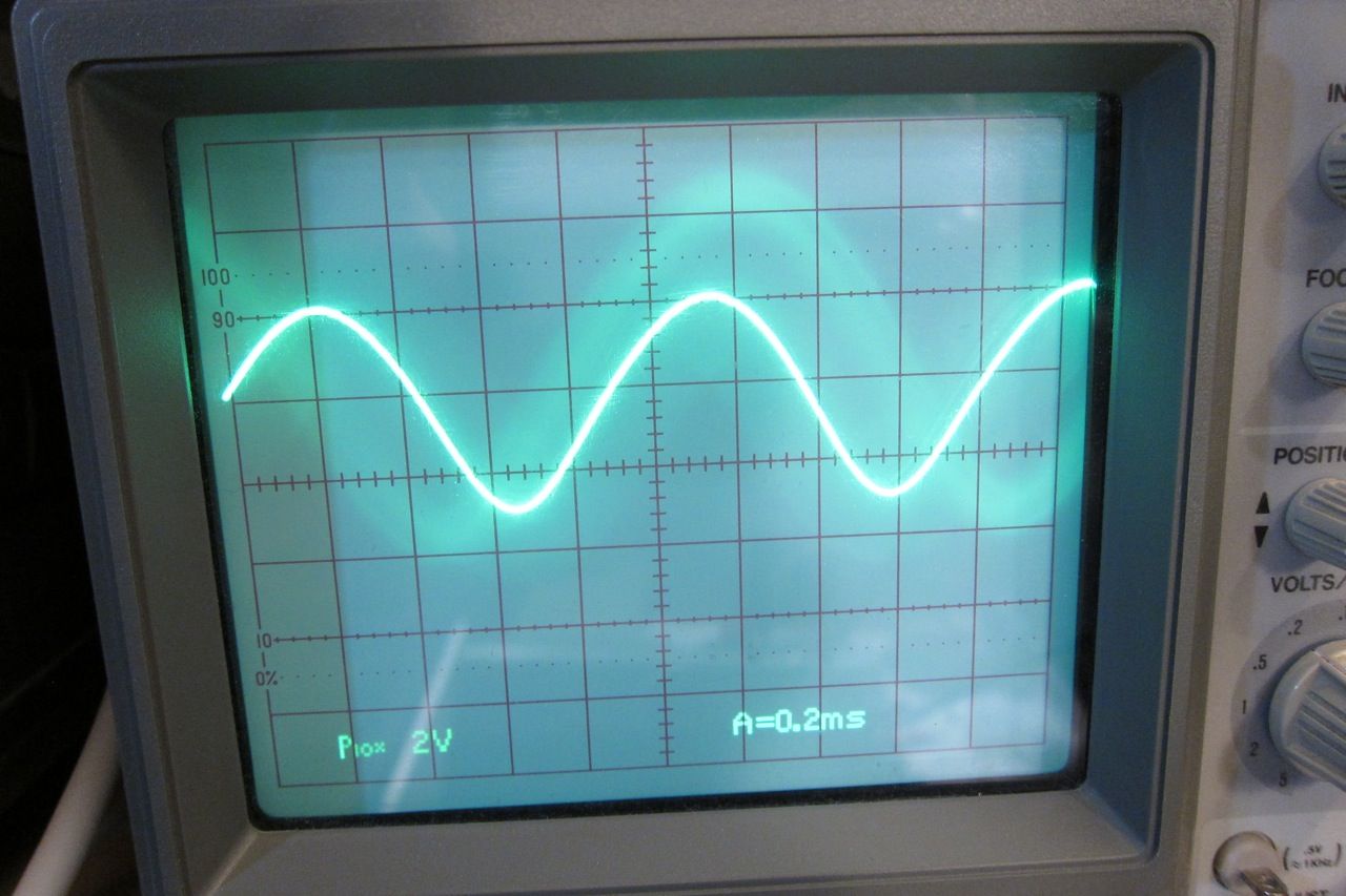
The distortion residual has lost it's humps and is looking very smooth.
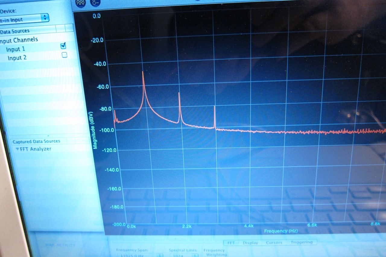
The 4th harmonic is no longer visible, and the 2nd and 3rd are greatly reduced.
Increasing further -
Distortion now .08%
Residual very similar to above, but even more smooth. (A little bit, anyway…)
FFT showing the 2nd and 3rd harmonic even lower. Neat!
So the logical thing is to just crank it all the way up, right? Well, yes and no. Here are the reasons (and people with more experience please correct me if I'm wrong.)
1) Heatsink - at some point you are going to get too hot. With the 5U that wasn't an issue. A good rule of thumb is the transistors 65C max and heatsinks 55C max.
2) Bias current vs. VA of transformer. You don't want your total bias current (in watts) to be more than 1/2 or maybe 2/3 or your transformer's VA rating.
3) Transistor dissipation. Make sure you look at the datasheet for the output transistors, they all have an absolute maximum and a de-rating as they get hotter. For long life don't set more than 1/2 the max dissipation.
4) Point of diminishing returns. In this example the measured distortion continued to decrease (down to .045 or so) as bias was increased to 370mV, but the gains were very small and it would added lots of heat. The sweet spot was closer to 300mV bias.
66deg,
That is a good question and it would be best if someone has measured the output voltage swing.
Will that flewatt tube amp work with the f4, yes it will. Will it sound good, maybe (the measures distortion is at 10%), and will it push the f4 to max power, probably not (rough power P=E^2/Z calculation says no).
I’d suggest building a tube pre-amp.
Thanks for the reply,
I am thinking of pairing it with some cube F8 drivers (94db) and I rarely play very loud at all, my reasoning for the Elekit is that I already have it so I might as well give it a go and see what happens, if its no good I then have the perfect excuse to build something else.
I am thinking of pairing it with some cube F8 drivers (94db) and I rarely play very loud at all, my reasoning for the Elekit is that I already have it so I might as well give it a go and see what happens, if its no good I then have the perfect excuse to build something else.
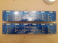
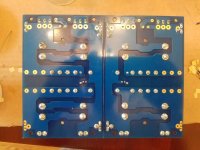
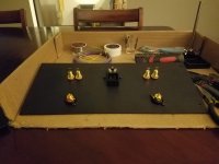
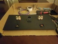
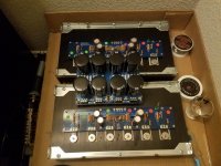
Ready for assembly
Finished the hardest part (I think). Just waiting on my Mosfets to arrive from Isreal to put everything together and start testing...
Finished the hardest part (I think). Just waiting on my Mosfets to arrive from Isreal to put everything together and start testing...
Attachments
-
 20190507_154143.jpg636.7 KB · Views: 97
 -
 20190507_154117.jpg802.8 KB · Views: 107
 -
 20190507_151435.jpg862.9 KB · Views: 115
 -
 20190507_142542.jpg670.9 KB · Views: 118
 -
 20190507_142525.jpg763.4 KB · Views: 115
 -
 20190507_135254.jpg916.3 KB · Views: 101
 -
 20190507_155614.jpg739.1 KB · Views: 116
 -
 20190507_155652.jpg762.3 KB · Views: 117
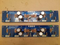
Finished the hardest part (I think). Just waiting on my Mosfets to arrive from Isreal to put everything together and start testing...
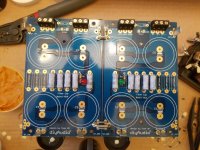
The easiest part of building an amp probably varies from person to person as much as personalities. My least favorite parts are sourcing parts and metal work...I'm sure others enjoy that. The easiest and most enjoyable to me is stuffing the boards. You're probably 25% complete!
then just go fishing
that's hobby with much easier and secure outcome

Not necessarily
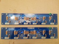
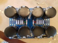
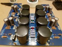
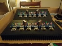
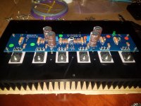
Unbeknownst to me, my MOSFETS came in the mail while I was soldering this afternoon... couldn't fume out my girl out with any tonight, but got a decent amount put together.
Attachments
Pass DIY Addict
Joined 2000
Paid Member
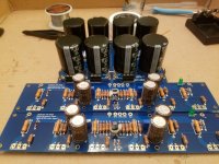
Looks like you've got most of the work done! My recommendation at this point is to wire/power ONE CHANNEL AT A TIME. If you have a dim-bulb tester or a variac, now is the time to use them to make sure you don't blow something up. I like using the dim bulb tester with the variac. This will let you see if there are any significant power problems and often provides "just enough" voltage to connect an input and a old test speaker to see if it makes sound.
Having some issues with an F4 build and looking for suggestions on how to troubleshoot. PS measures 25.2V. However, when connected to the audio boards I have 0mV Bias and 25V offset no matter how P1 and P2 are adjusted. Checked continuity for all ground points and V+ and V- from PS to Audio boards. Not sure what to look at next. 
- Home
- Amplifiers
- Pass Labs
- A guide to building the Pass F4 amplifier