Thanks jac, any idea if there's a considerable to increasing the f4 input to 100k. I would think that the increased Johnson noise wouldn't be too much of an issue because of the unity gain and the signal to noise would be suitably high.
Is increasing rc significant.if at 100k the f3 is 3.5hz then at 47 f3 is about 7hz.is that really a problem?
Is increasing rc significant.if at 100k the f3 is 3.5hz then at 47 f3 is about 7hz.is that really a problem?
Thanks jac, any idea if there's a considerable to increasing the f4 input to 100k. I would think that the increased Johnson noise wouldn't be too much of an issue because of the unity gain and the signal to noise would be suitably high.
Is increasing rc significant.if at 100k the f3 is 3.5hz then at 47 f3 is about 7hz.is that really a problem?
I don't have enough knowledge to fully answer the question, but what I have been told is that you want about 1 decade lower F3 frequency than your system can reproduce. Apparently, it isn't so much the loss of bass amplitude, but the phase shift that affects the sound quality. Of course, if you can't hear the difference between 3.5 and 7 Hz, then it won't matter.
Jac
Are you referring to R2?Thanks jac, any idea if there's a considerable to increasing the f4 input to 100k. I would think that the increased Johnson noise wouldn't be too much of an issue because of the unity gain and the signal to noise would be suitably high.
Is increasing rc significant.if at 100k the f3 is 3.5hz then at 47 f3 is about 7hz.is that really a problem?
post1 sch shows this as 47.5k.
That 47k5 is in parallel with the input source.
If the source has an output impedance of 200ohms, then the amplifier sees a source impedance (substantially resistive) of 200r||47500r = 199r15
The 47k5 has virtually no noise effect on the amplifier's input.
Change to 100k, or 1000M, and still the source determines the resistance seen by the amplifier.
Adding in a DC blocking capacitor before the amplifier input is often recommended.
1uF & 100k gives a similar roll off as 2u2F & 47k and either of those allow the full audio band of 20Hz to 20kHz to pass.
Thanks for the Help
Just wanted to say thanks to mrdave45 and zen mod for your advice in fixing my goof. I got all the diodes and TL341 replaced and was able to go through the bias setting process successfully. Like many others, I needed to reduce R9, in my case to 5.6k. Now I have to put the F4 together with the Impasse.
6L6,
A couple of things you might consider adding to the early part of the thread, if you can edit.
1. Add a recommendation to use a light bulb tester. This subject continues to surface, including my goof.
2. Remove the light bulb tester before trying to set bias and DC offset.
3. Plan on having resistors between 5k and 7k available for R9. Many of us can't get enough bias with R9 at 10k. If that's the case, reset P1 to max resistance and install a smaller R9.
I mention these things because they keep coming up in the thread. It would be great if they were part of the bias setup section of your original build guide.
Thanks,
Jac
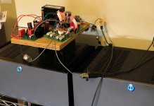
Impass + F4
I finished my Impasse + F4 build. That's a lot of stuff to squeeze into a 4U case. In this case, I am running the Impasse as a voltage gain stage for the F4.
I had been worried about putting a 350 transformer "in the box" and the potential for noise issues, but this hasn't been a problem. No hum at all. Just a very faint white noise that is probably from one of the tubes. Twisting wires is a good thing.
Attachments
Impressive! What are you using for volume control and source selection I see XLR inputs but it appears to be a "regular" stereo F4.
Thanks. I enjoyed the build.
I have a Relaixed2 pre that I like for volume control and source selection. In case you aren't familiar, the Relaixed 2 uses a relay controlled step attenuator for volume control.
My system is mostly balanced with XLRs. One of the advantages of the Impasse is that it is designed to be balanced input and your choice of single ended or balanced output, so I am picking off the single ended signal for the F4. If I ever decide I want more power, I can add a second F4 using the balanced output.
Jac
I finished my Impasse + F4 build. That's a lot of stuff to squeeze into a 4U case. In this case, I am running the Impasse as a voltage gain stage for the F4.
I had been worried about putting a 350 transformer "in the box" and the potential for noise issues, but this hasn't been a problem. No hum at all. Just a very faint white noise that is probably from one of the tubes. Twisting wires is a good thing.
Nice work!

I don't have the courage to put everything in one box!
 Glad it worked out!
 Best,
Anand.
I have a relaixed passive so I know the projects quite well.
Thanks. I enjoyed the build.
I have a Relaixed2 pre that I like for volume control and source selection. In case you aren't familiar, the Relaixed 2 uses a relay controlled step attenuator for volume control.
My system is mostly balanced with XLRs. One of the advantages of the Impasse is that it is designed to be balanced input and your choice of single ended or balanced output, so I am picking off the single ended signal for the F4. If I ever decide I want more power, I can add a second F4 using the balanced output.
Jac
Parallel components
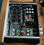
Hi 6L6, from the above schematic, there are parallel 3W resistors and Caps...which don't show up in F4 manual nor on the PCB's...any specific reason, they have been explicitly called out in the diagram?
Building the Pass/Firstwatt F4
This is a fantastically good sounding amp - read more about it here before staring;
http://www.firstwatt.com/pdf/prod_f4_man.pdf
The thread at DIY audio -
F4 power amplifier
And this the the corrected schematic (The schematic in the Firstwatt article has a typo, also this one agrees with the PCB)
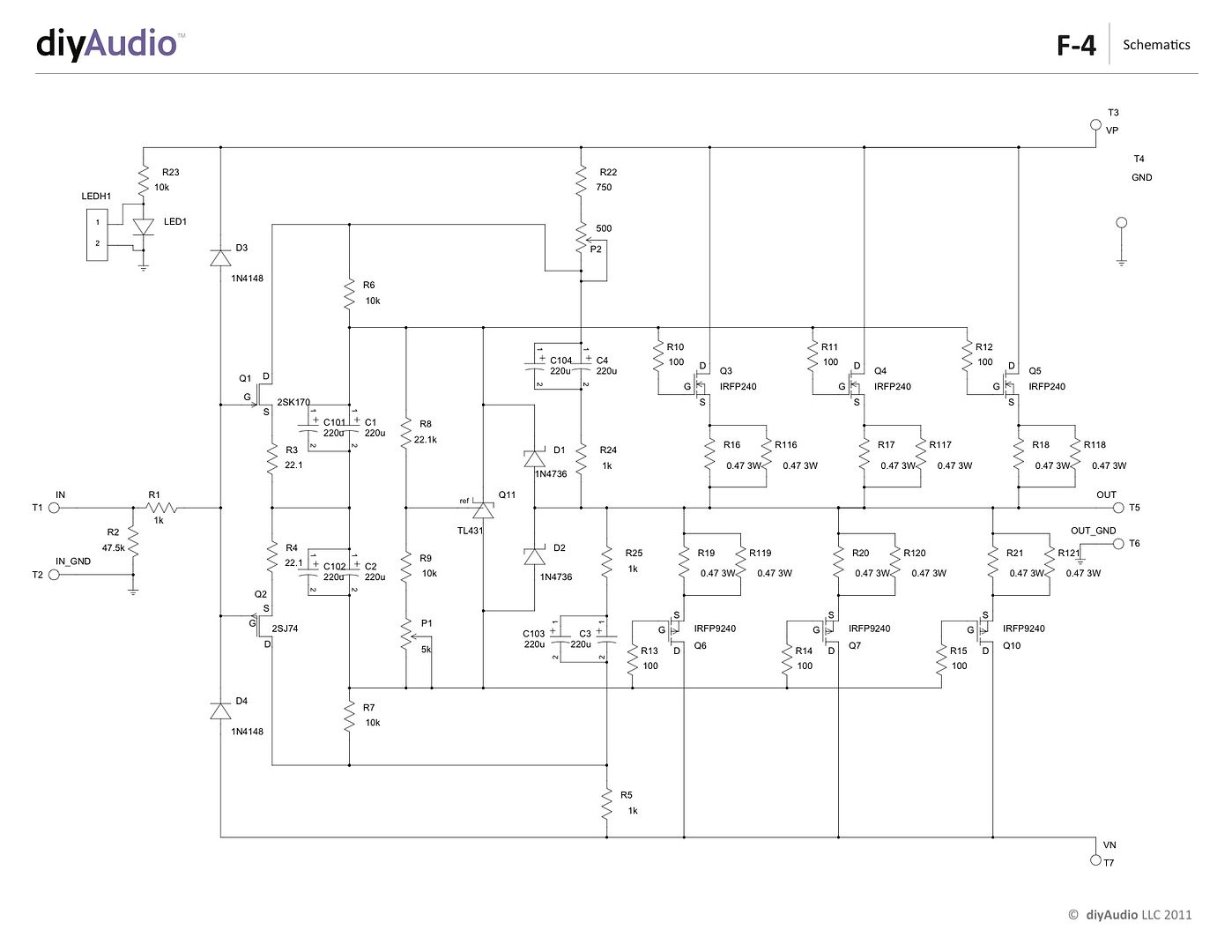
Hi 6L6, from the above schematic, there are parallel 3W resistors and Caps...which don't show up in F4 manual nor on the PCB's...any specific reason, they have been explicitly called out in the diagram?
If at some point you decide to experiment with the biamp configuration vs bridged could you post the results. I think as my speakers are very sensitive, I think bridged may be a bit overkill (a single f4 drives my open baffles really quite loud) but I am very interested in how setting 2 up biamped performs. Cheers.
Will do Dave. Currently listening through a pair of JBL L-220 that I rebuilt the crossovers several years back. OBs are on my list, I have a pair of silver Augies and once funds are available purchase from the store a pair of SAL c08. Plus I think the active crossover Mr. Pass says will be available next year would be a nice pairing.
Tnx
David
Tnx
David
Because the way the PCB is lay out, there are multiple pads to afford for different lead arrangements on those particular caps and resistors. It's not physically possible to parallel them on the PCB.
Thanks 6L6, I need to stop drinking while building....
In the beginning of this thread it's stated that the bias sweet spot is close to 300mv. Since 6L6's build was completed with the 5U Deluxe chassis what's the maximum recommended bias for the 4U Deluxe chassis? I don't want to compromise the transistor life long-term due to excessive heat.
Also, if I build the F4 or BA-3B balanced to obtain close to 100W is this possible with the 4U chassis? Does balancing the amplifier increase the heat-sink requirements?
It's an expensive mistake if I purchase the wrong chassis...
Also, if I build the F4 or BA-3B balanced to obtain close to 100W is this possible with the 4U chassis? Does balancing the amplifier increase the heat-sink requirements?
It's an expensive mistake if I purchase the wrong chassis...
Pass DIY Addict
Joined 2000
Paid Member
Nelson answered this question some time ago with the following set of descriptors:
Blimey hot is 10s hands on = 45 deg C.
Crikey hot is 5 sec = 50 deg C.
Bloody hot is 2 sec = 55 deg C.
X*?@! is 60 deg C.
Aim for no more than "Crikey Hot" ...
Of course, if you are looking to make this determination BEFORE HAND, multiply the cumulative power burn for each transistor that will be mounted on a single heatsink by the thermal dissipation (c/w) of that sink.
For example, the following are measurements I made with my F4:
200mV = 56w per channel
225mV = 63w per channel
250mV = 70w per channel
275mV = 77w per channel
300mV = 84w per channel
My F4 uses two 3U sinks from the DIYAudio store per channel. Each sink is rated at 0.50c/w, thus I have sinking capability of 0.25c/w per channel. If I run at 300mV bias, I get 84w per channel that is dissipated by 0.25c/w worth of heatsinking. Thus, expected heat sink temp rise will be somewhere near 21c over ambient. Assuming "standard" room temperature somewhere near 20-25c, this results in a final temp of somewhere between Blimey and Crikey hot - about the upper limit of two 3U sinks per channel.
The 4U chassis uses two sinks, each rated at 0.31c/w. Dissipating 84w (300mV bias) on a 0.31c/w sink results in a temp rise of 26c - likely crossing the 50c barrier, so larger sinks are desirable for longevity of your output devices.
If you want more bias from the F4, you'll need to move to greater levels of sinking.
Last edited:
4U is , by my experience , good for 80W per side , maybe little less if you live in India
so , considering usual approx. 45Vdc in PSU , that would be 80VA/45V ......... little less than 2A for Iq say that's 1A8
1A8 divided with 3 verticales is 0A6
0A6 across 0R47 source resistor is giving ya 282mV
also , 22V5 across each mosfet , and 0A6 through each mosfet is giving ya 13.5W of heat ....... which is , funny , extremely close to 80W , from the beginning

if you can cool it - crank it to have up to 35W heat per mosfet ........ and those mosfets will certainly outlive me and maybe even you
in a meantime , staying in 4U De Luxe chassis , just chill ; it'll work as 100W monoblock , no sweat
at least no different sweat vs. using it as stereo amp
so , considering usual approx. 45Vdc in PSU , that would be 80VA/45V ......... little less than 2A for Iq say that's 1A8
1A8 divided with 3 verticales is 0A6
0A6 across 0R47 source resistor is giving ya 282mV
also , 22V5 across each mosfet , and 0A6 through each mosfet is giving ya 13.5W of heat ....... which is , funny , extremely close to 80W , from the beginning
if you can cool it - crank it to have up to 35W heat per mosfet ........ and those mosfets will certainly outlive me and maybe even you
in a meantime , staying in 4U De Luxe chassis , just chill ; it'll work as 100W monoblock , no sweat
at least no different sweat vs. using it as stereo amp
- Home
- Amplifiers
- Pass Labs
- A guide to building the Pass F4 amplifier