This amp is underrated. People have said it before, and they are right.
The soundstage is incredible. Solid, consecutive, almost holographic.
I’m looking forward to building different preamps already.
And lastly, damn, now I’ll have to build an F4 speaker amp, it’s just too good. I should have a kit stashed away somewhere…
Yeah.
I love mine too, although it deviates from stock with zero degeneration.
Very nice tidy build.
margol, I had the FQA12P20 and FQA19N20C left over from a previous F5 build. Since I’m only using a single pair of output FETs, and since they’re pretty much drop in replacements for the IRFP240/9240 parts, I thought I’d put them to good use again.
On paper the FQA12P20 and FQA19N20C are the better parts, with lower R_DSon, higher transconductance, and lower input and output capacitance. The IR IRFP9240 also has that weird and well documented transconductance issue at midrange frequencies, which results in higher THD. So it may be preferable either use a different manufacturer for the p-channel part, or to look for a different type of FET that doesn’t show that issue.
And thanks for the compliment 2 picoDumbs")
When you say zero degeneration, do you mean that you’re not using source resistors? Or that it’s 100% stock? Did you build yours as a headamp too?
On paper the FQA12P20 and FQA19N20C are the better parts, with lower R_DSon, higher transconductance, and lower input and output capacitance. The IR IRFP9240 also has that weird and well documented transconductance issue at midrange frequencies, which results in higher THD. So it may be preferable either use a different manufacturer for the p-channel part, or to look for a different type of FET that doesn’t show that issue.
And thanks for the compliment 2 picoDumbs
When you say zero degeneration, do you mean that you’re not using source resistors? Or that it’s 100% stock? Did you build yours as a headamp too?
Not using source resistors.
Not as a headphone amp. but if I was building a headphone amp, I would do exactly as you have done.
You really don't need voltage gain for 90% of headphones
A straight buffer is the ideal solution, especially if a DAC is your source.
I am using mine on high efficiency speakers without any voltage gain just like you. It sounds awesome.
Last edited:
This amp is underrated. People have said it before, and they are right. The soundstage is incredible. Solid, consecutive, almost holographic…
Congrats! Great to hear another success story. I just have one small edit for my experience: "The soundstage is incredible. Solid, consecutive, *incredibly* holographic…" I just get an amazing image, with almost 6 feet of depth on some recordings. Still loving these amps every day.
Here's a description of the rest of my system in case that helps serve as a reference for anyone: A WIP System: Work In Progress (Denver, CO) - Virtual Systems
margol, I had the FQA12P20 and FQA19N20C left over from a previous F5 build. Since I’m only using a single pair of output FETs, and since they’re pretty much drop in replacements for the IRFP240/9240 parts, I thought I’d put them to good use again.
On paper the FQA12P20 and FQA19N20C are the better parts, with lower R_DSon, higher transconductance, and lower input and output capacitance. The IR IRFP9240 also has that weird and well documented transconductance issue at midrange frequencies, which results in higher THD. So it may be preferable either use a different manufacturer for the p-channel part, or to look for a different type of FET that doesn’t show that issue.
And thanks for the compliment 2 picoDumbs
When you say zero degeneration, do you mean that you’re not using source resistors? Or that it’s 100% stock? Did you build yours as a headamp too?
Rodeodave,
Great work! Everyone reading this forum needs to get off the fence and build an F4 (stop over thinking it, just build it) The F4 with a tube linestage = Magic!
This past weekend I finally got around to finishing the F4 headamp build that I’ve had on my bench for several weeks now.
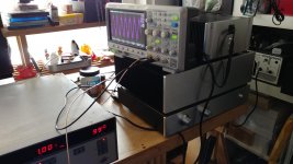
The PSU consists of a 150VA 2x15VAC toroidy transformer with a CCRC filter. There are 3x33000uF filter caps per polarity, R being a 1R wire wound bolted to the bottom plate. Supply voltage at the last C is a symmetrical +/-18V.
The amp is using a single pair of FQA12P20 and FQA19N20C output FETs with Vishay CPF3 0R22 source resistors. The output FETs’ bias is set at 0.5A (110mV over the source resistors). The input JFETS have an Idss of about 8.5mA, with the p-channel having a 5R degeneration resistor to match the j74’s transconductance to that of the k170’s (see 5th image). I had to use 7k5 for R9 to get the bias up to 0.5A. Output offset is around 1mV when warmed up. I have 15mV of cold output offset in my notes, but I have to check that again, it just seems too low.
The numbers:
(THD measured with Boonton 1121 analyzer with 0.0009% THD baseline, F4 unloaded output)
Vsupply=+/-18.01V
Ibias=0.5A (110mV over R22)
gain -0.46dB (1V in, 0.948V out)
noise about 50uV unloaded (purple trace 6th image)
1V input (0.948V out) @ 1kHz:
95.46dB S/N
94.92dB SINAD
-94.9dB THD, 0.0019%
3V input (2.847V out) @ 1kHz:
105.56dB S/N
93.97dB SINAD
-93.98dB THD, 0.002%
THD spectrum 2nd>3rd>4th, with 2nd around 10dB over 3rd
visible clipping at 14V input (1.213% THD), above 7V input 3rd order dominant
output impedance: 0.33 Ohm
unloaded V1=521.2mVrms @50Hz
8R2 loaded V2=500.5mV
Z=R*(V1/V2-1)=0.33R
There are countless reviews on the F4, so I’ll keep it short. Source is a soekris 1021 R2R DAC with a DCB1 output buffer. Surprisingly, there’s enough voltage swing for the HD800, with a few dB to spare.
This amp is underrated. People have said it before, and they are right.
The soundstage is incredible. Solid, consecutive, almost holographic.
I’m looking forward to building different preamps already.
And lastly, damn, now I’ll have to build an F4 speaker amp, it’s just too good. I should have a kit stashed away somewhere…
Hi, great job!
I'm looking for this build, may I ask you where did you sorce the transformer, case, psu and amp boards ?
Since I live in Germany, closer to you than to our english-speaker friends
Thanks,
Mike
Well, the transformer is an audio grade transformer from toroidy in Poland.
The case is from aliexpress, customized model 2412B and measures 240*120*271 mm. There should be something similar available from Modushop in Bolgna, maybe a mini dissipante.
The PSU is a Brian GT Aleph PSU board, I think I got it from chipamp.com years ago.
And the amp boards are the F4 pcbs designed by Peter Daniel. I got them years ago from the Swap Meet.
The only two changes that make this amp more suited for headphone use are first and foremost the reduced number of output pairs, and to a lesser extent the lower value source resistors. It will work with speakers too, especially high efficient ones, but there will be less juice available (about 1A). One might also mention the lower supply voltage (18V vs. 23V), so there will be a lower output voltage swing before clipping sets in.
The number of output pairs and the bias current is directly connected to the available output current. The original F4 will do 4A peaks (about twice the total bias), way too much for headphones. So a single pair will suffice.
Generally, the source resistors ensure proper current sharing between paralleled FETs. Since their internal rsistance drops with temperature, they will start to hog current. If they are not tightly matched, one will draw more current that the others, heat up and draw even more current. The source resistors help in that they will develope a higher voltage drop with passing more current, effectively reducing the drain-source voltage, which results in less current draw.
With multiple output pairs, the internal resistance and the source resistors are in parallel, thus reducing the output impedance.
With a single pair, or even with very tightly matchd FETs, we can use lower value source resistors, or even do without them. This will result in a comparably low output impedance (0.33R vs. 0.2R).
And that brings me to a question for 2 picoDumbs: How did you manage to get the amp thermally stable without using source resistors? Are you simply using tightly matched 240/9240 pairs? I would love to hear or see some details.
I bought a tube of mosfets for both N and P channel parts (same batch)
1) Sort into Vgs Threshold values
2) Do curves of Id vs Vgs
3) Select closest matching parts
4) Then test current sharing under intended operating conditions
5} If necessary keep swapping in new mosfets to find the match that shares current better than 5% difference.
I run 2 pairs instead of 3, at 2A bias.
I also have a 2N/3P output.
Last edited:
Rodeodave, thanks for explanation.
I've seen an opinion that scaled down f4 is not well suited for head amp because of high noise level, which will manifest it self with headphones.
Is that your experience as well?
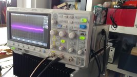
High noise?? This amp has one of the lowest noise floor out there, something like 50uV.
The first image attached shows the noise floor of the amp with unloaded output and the input floating. The vertical scale on the scope is 500uV (that's 0.5mV per division). The hash around the bright purple trace is scope amplifier noise. It's hardly measurable.
The second image attached is the unloaded output with a 1mV (rms, so like 1.4mV peak) signal at the input. Same 500uV scale.
With the HD800 the amp is dead quiet. It's impossible to tell whether it's on or not, of if the headphones are plugged in or not. What you can tell though is when the track that's being played is starting, because as soon as they turn up the controls on the mixing console in the studio, you will hear any faint amount of noise or creaking of chairs or ambient in the recording.
Attachments
Rodeodave, thanks for explanation.
I've seen an opinion that scaled down f4 is not well suited for head amp because of high noise level, which will manifest it self with headphones.
Is that your experience as well?
That will depend on power supply implementation, nothing to do with amp circuit.
The current requirements to bias for headphones are so low, that power supply ripple will be reduced significantly.
It is going to depend solely on implementation.
The F4 is a very quiet amplifier... do you have a link to that opinion? I’d like to see if there was more information or some interesting circumstances.
I saw it long ago and can not find it now. But, as I recall, here was no additional information, just the statement
You can swing closer to rail voltages.
Sonic impact, I haven't compared with a listening test.. It doesn't seem to add additional distortion or anything obvious to the performance specs. Not that I have observed so far
You don't need them, but I think they might also function to provide some additional rc filtering before the bias circuit.
I might simulate psrr of them in an out.
Last edited:
I would love to hear or see some details.
Some more info.
This is my 2/3 version. Hahaha.
Sounds bloody beautiful.
This one is Zero degeneration on P Channel Mosfets and a little bit of degeneration on N Channel Mosfets (Just 50 mOhms on the N Channel mosfets. Intentionally tweaked this way for sonic reasons)
F4 Beast Builders
F4 Beast Builders
F4 Beast Builders
I have another F4 version I am building at the moment too.
Once I finish building all of them I will perform a listening shoot out.
All up I have 4 different versions
Last edited:
One done. One more to go!
When I am running two amps in parallel do I need a resistor on each amp out put for load sharing?
- Home
- Amplifiers
- Pass Labs
- A guide to building the Pass F4 amplifier