Ok, good. How stable should DC offset be once the amp reaches normal operating temperature? Within a couple mV if I watch the meter? Offset seems to vary continuously even at full temperature, although the change is then quite small.
At any rate, it sounds quite nice.
My favourite amp of all time
") i have 4 of them, and the SMD version.
i have 4 of them, and the SMD version.
Ok, good. How stable should DC offset be once the amp reaches normal operating temperature? Within a couple mV if I watch the meter? Offset seems to vary continuously even at full temperature, although the change is then quite small.
At any rate, it sounds quite nice.
that's normal
My favourite amp of all time
I'm an Aleph guy too.. NP really spoiled some of us. Barring any wand-waving over a jfet vfet Aleph (hint hint) I'm pretty content with mosfet dub sounds over 3-way, a match made in heaven so far. "just a little loose".. at this point its almost old-school.
Last edited:
I'm an Aleph guy too.. NP really spoiled some of us. Barring any wand-waving over a jfet vfet Aleph (hint hint) I'm pretty content with mosfet dub sounds over 3-way, a match made in heaven so far. "just a little loose".. at this point its almost old-school.
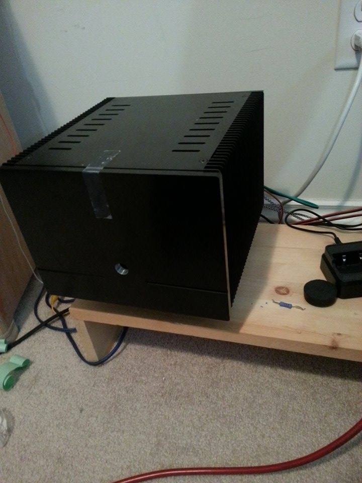
I love my Cube amps

Pass DIY Addict
Joined 2000
Paid Member
you could also install a trimmer pot for R13 to dial in bias.
This was going to by my advice as well, this way you can bias it up to the limits of what your sinks can dissipate.
This was going to by my advice as well, this way you can bias it up to the limits of what your sinks can dissipate.
thats what I'm going to be doing
later this week tho, very busy at work, to many calls to do.Two years ago I opened this post. I see that has resumed, so....this is mine Aleph Mini
pugno - Mini Aleph...per un pugno di watt
Thanks again!!!
pugno - Mini Aleph...per un pugno di watt
Thanks again!!!
Two years ago I opened this post. I see that has resumed, so....this is mine Aleph Mini
pugno - Mini Aleph...per un pugno di watt
Thanks again!!!
what were your rail voltages ?
what were your rail voltages ?
A little less than 17V with a 300VA transformer when bias is set at 1,3A, clipping at 29,6Vpp. The initial problem was an error on the resistances that regulate the AC bias. With valor indicated on PCB (china ones...) it was to hight, more then the limit of 66% (indicated for "weak" supply). Putting on the right value you find in "kk" scheme (1,5Kohm each one) the AC bias is 50% and my problem was solved.
Visual Analyzer measure of THD:
Vpp Out PWR rms THD
5V 0,32W 0,019%
10V 1,3W 0,048%
15V 2,85W 0,065%
20V 5W 0,098%
25V 8W 0,14%
29,5V 11W 0,56%
Giovanni
Last edited:
A little less than 17V with a 300VA transformer when bias is set at 1,3A, clipping at 29,6Vpp. The initial problem was an error on the resistances that regulate the AC bias. With valor indicated on PCB (china ones...) it was to hight, more then the limit of 66% (indicated for "weak" supply). Putting on the right value you find in "kk" scheme (1,5Kohm each one) the AC bias is 50% and my problem was solved.
Visual Analyzer measure of THD:
Vpp Out PWR rms THD
5V 0,32W 0,019%
10V 1,3W 0,048%
15V 2,85W 0,065%
20V 5W 0,098%
25V 8W 0,14%
29,5V 11W 0,56%
Giovanni
Ok thanks... Mine are at 21V rails and going to raise the bias to about 1 - 1.3
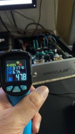
45C is getting up there. Hopefully there's some room to up the current to 25w/device. Saving grace, at least you're in Canada.. it's hard/costly enough keeping a house cool here much of the year. Actually that's another reason to have trimmers.. your fall/winter leaves a lot of room to work with, pun intended.
Last edited:
45C is getting up there. Hopefully there's some room to up the current to 25w/device. Saving grace, at least you're in Canada.. it's hard/costly enough keeping a house cool here much of the year. Actually that's another reason to have trimmers.. your fall/winter leaves a lot of room to work with, pun intended.
They sure do get warm
Hello. I apologize for my bad english ..... I built a mini aleph using this scheme. Two identical board, same problem
This is the input and output curve at 10Khz. 17,5V each rail, 850mA bias, under 5mV DC offset. 3Vpp input, 27Vpp output.(input on the bottom side)
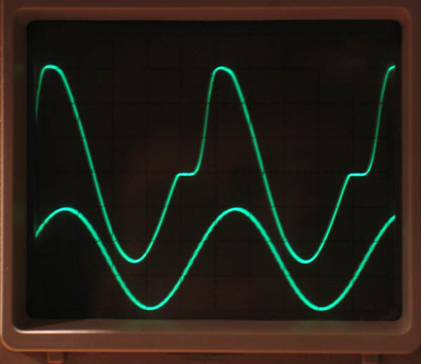
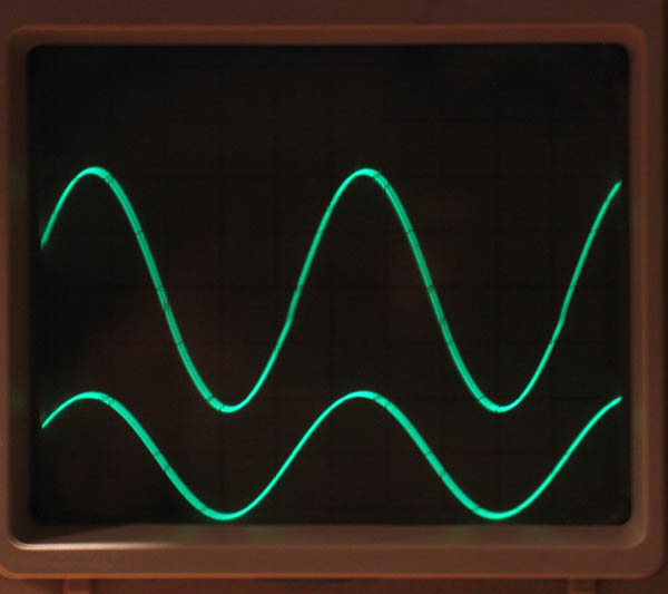
Same values but 1Khz input signal:
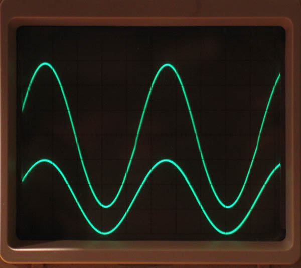
10Khz, 2Vpp input, 20Vpp output:
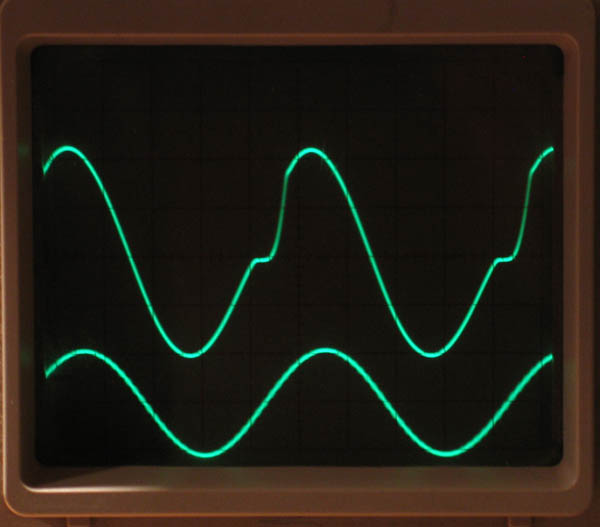
1Khz, 2Vpp in, 20vpp out:
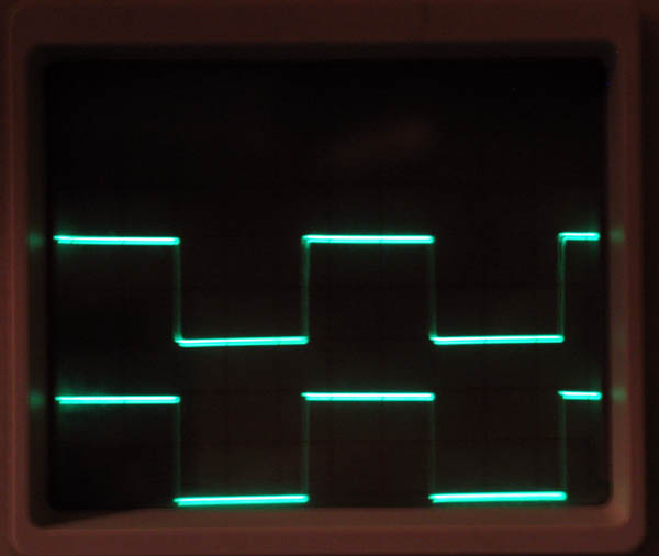
1Khz square, 1Vpp in, 10Vpp out...it seems good.
The problem manifests itself around 5Khz and I can find it just in the output side of the differential pair of irf9610, matched under 3mv difference.
Does anyone have any idea?
Thanks.
Giovanni
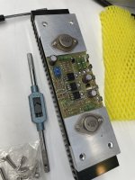
My pass am 15-20watt, I read this schematic same part only tr final using tr irf250. sound is good run 1-2 hours heatsink around 47-50 under 60 degrees.
I’m Buy from china one pair $32 USD
PSU use capacitance multiplayer c5200set
Xformer 18ct @25v.
Attachments
- Home
- Amplifiers
- Pass Labs
- Mini Aleph, some output problem